The Rapid Execution and Combat Targeting (REACT) was an enhancement program of the U.S. Air Force. Its objective was to renew the SAC’s Minuteman missile launch control centers.
The Strategic Air Command (SAC) initiated the program in the 1980s at the cost of 632 million dollars. As a result, the 1960s and 1970s vintage nuclear control systems gave place to modern ones.
Certainly, the new systems allowed rapid and flexible retargeting for both individual missiles and the entire force. But they did more than that. They also lent a hand to missile crews with their workload.
This is the story of how U.S. launch control centers got to have a floppy disk drive and a trackball!
Meet the missileers
First of all, it is necessary to have a little perspective. Each SAC Minuteman missile had its own unmanned launch facility (LF). At the same time, each missile was at least three miles from another one and three miles from their respective launch control center (LCC).
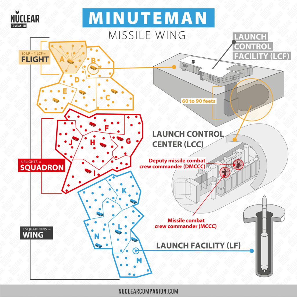
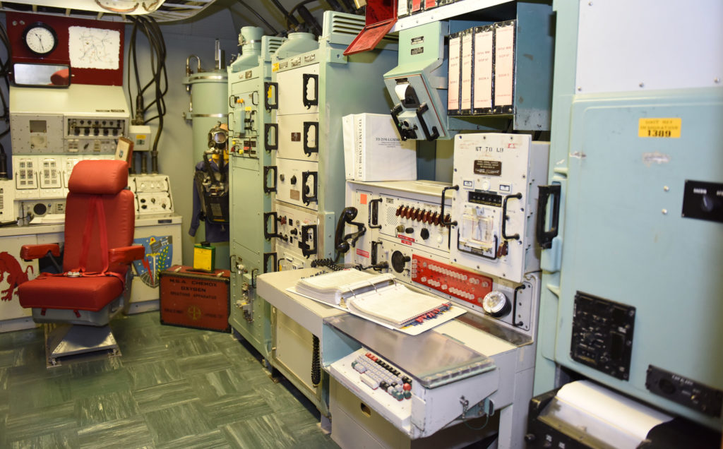
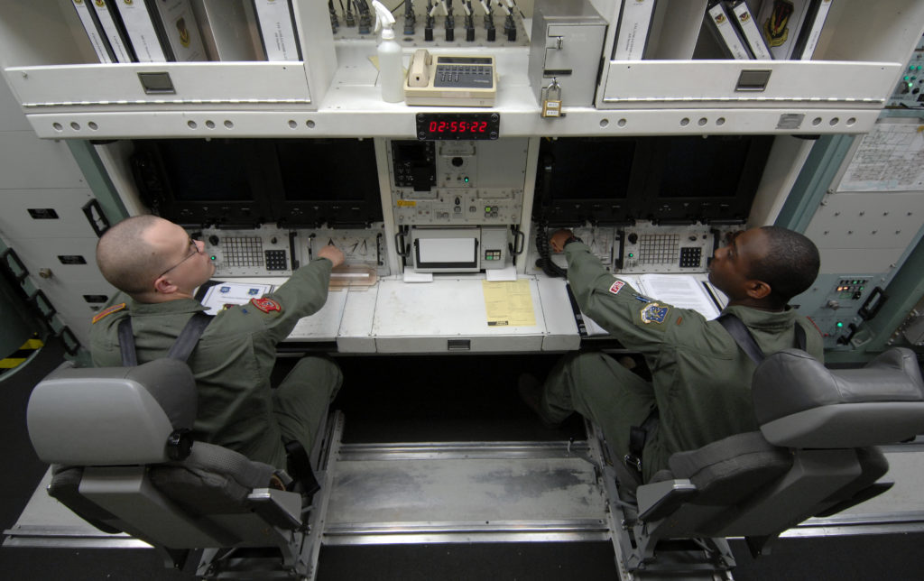
The LCC was an underground facility manned by a missile combat crew (MCC). The crew consisted of a missile combat crew commander (MCCC) and a deputy missile combat crew commander (DMCCC).
In short, each LCC was responsible for 10 missiles (a “flight”). Likewise, five LCCs formed a squadron and three squadrons conformed to a wing.
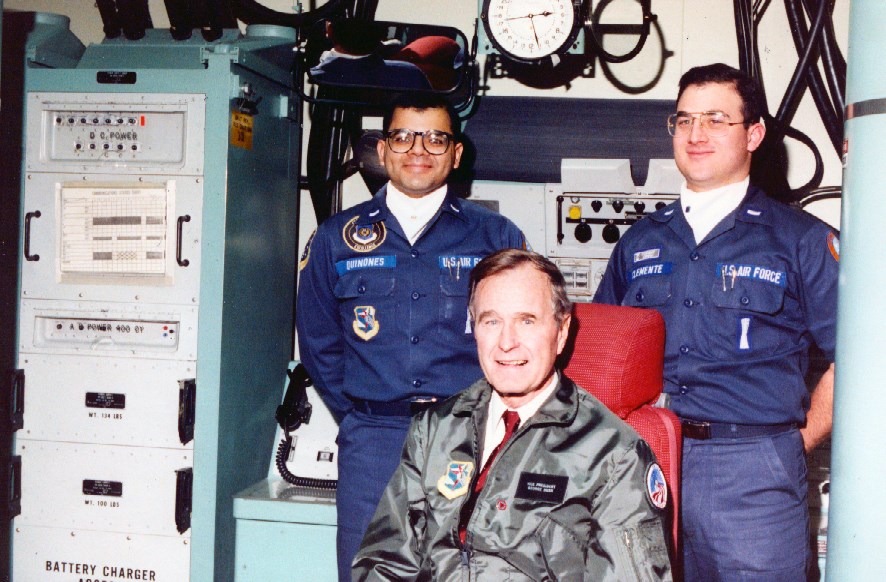
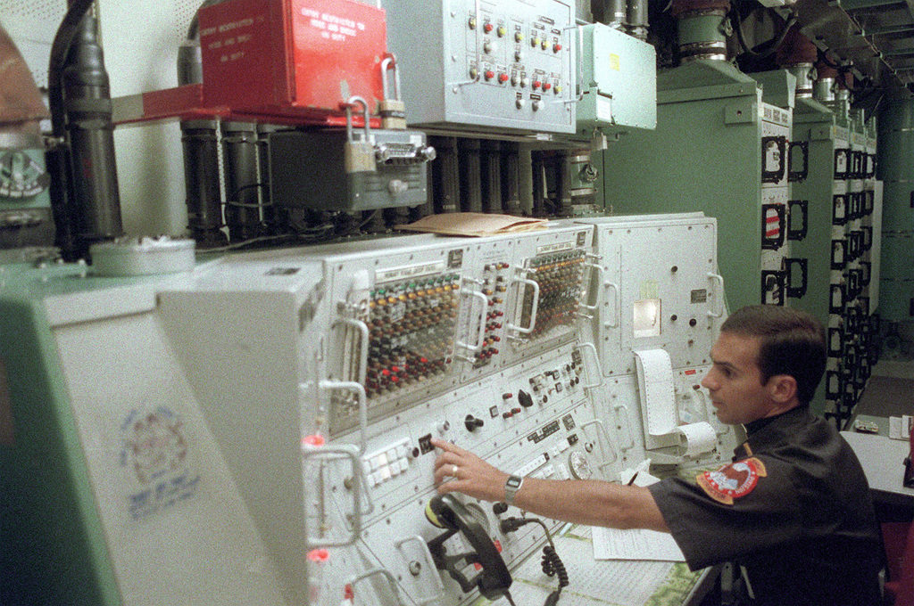
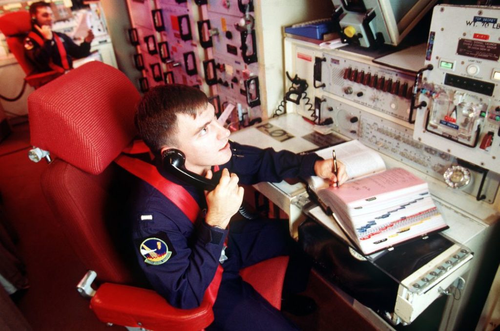
Each combat crew, several feet away from each other, had its own launch control console. When a Higher Authority sent a message, it appeared in several racks in the LCC.
In these cases, a crew member had to get up to get all the received messages to launch a missile. Then, the crew had to turn two keys at the same time in locks. Certainly, the trick was in putting the keys far enough apart so that one person could not turn both keys alone.
A Frankenstein System
Over the years, the workload and burden of SAC launch crews had grown. This was due to new equipment for command, control, and communications (C3) becoming part of the LCC.
By the mid-70s SAC implemented the RIVET SAVE modification, which reduced Minuteman crew members by a third. To achieve this reduction, the Minuteman alert tour passed from 36 to 24 hours. One crew member was in rest status (that is, sleeping) while inside the LCC.
Similarly, an equipment modification was necessary to end the need for a second launch crew on site. Also, to prevent the remote possibility of an unauthorized launch by a single crew member. The price to pay, though, was increasing crew requirements and workload.
And yet, RIVET SAVE was only the beginning. Modifications of ever-increasing complexity continued increasing the crew workload.
Later systems increased procedures and crew necessary actions such as:
- The SAC Automated Command and Control System (SACCS)
- and the Survivable Low-Frequency Communication System (SLFCS).
The Air Force was aware of this difficulty. Therefore, they need to integrate all these new gadgets and LCC racks into a two-man console. This was one of the requirements imposed on REACT.
But it was not the only one…
The retargeting problem
At first, operators could not retarget Minuteman missiles remotely. That is to say that, for reaching a target, its guidance system needed a reference of it in the silo. Also, the missile computer required a manually-replaced tape with the new targets.
This tape’s journey from its creation to its final stop was a process as cumbersome as they come.
First, the SAC headquarters in Omaha had to prepare the tape. After that, a targeting team should visit each silo with it. There, they had to go to the missile, take the pretargeting setup out, and put in the new one.
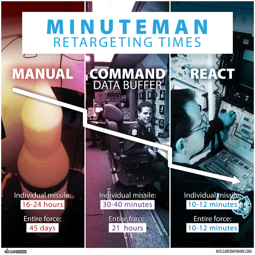
This time-consuming and tricky retargeting process could take 16 to 24 hours. To retarget all of Minuteman’s force took 45 days.
However, this low maneuvering speed was fair for the strategy of the moment. Missiles were to blast just once in a big strike against large and immovable urban areas.
Meanwhile, the new strategy of a “flexible response” required missiles able to cover any target. They already had the surveillance technologies to do so.
SAC introduced in the 1970s better missile guidance systems and the Remote Data Change (RDC) protocol. Also, the Command Data Buffer (CDB) System.
CDB’s key feature was to allow SAC headquarters to assign new coordinates to the wing headquarters or to the launch crew. In so, a computer would calculate the new trajectories and transmit them to the missiles.
As a result, with this method, a Minuteman III missile could change its target in 25 minutes. However, due to the 1970s computers’ low capacity, only one missile could do so at a time per squadron (a squadron consisted of five LCCs and 50 missiles).
Each wing could process its squadron in parallel. The Air Force estimated that the entire force of 500 missiles could change targets in 20.5 hours.
Yet, let us not forget that these numbers were for targets not pre-stored in the Minuteman computer. The pre-stored function allowed to select one of these target options in a matter of seconds. The Minuteman II had six options; the Minuteman III, had four.
Each of these four sets contained the target data for all three warheads in the missile. One was the primary set while the rest was a reserve.
Retargeting was not a rare task. On the contrary, it was part of the daily routine.
The 90th Strategic Missile Wing at F.E. Warren AFB in Cheyenne, WY, was required to retarget up to 22 Minuteman II missiles every month. This was part of the maintenance of guidance and control systems. While on it, those idle missiles received reassignment to other targets on alert.
Retargeting and launch response times needed to drop. Let’s not forget that the burden on the crew also needed to get lower. Consequently, SAC requested in the middle of the 1980s a new update program to enhance its Launch Control Centers.
The REACT Program
The ICBM Integrated Electronics Upgrade (I2EU) program
On 22 Aug. 1986, headquarters SAC issued a Statement of Operational Need (SON 06-85). They need it for an ICBM Rapid Message Processing and Retargeting (REACT) capability.
This requirement stated three major considerations:
- To reduce warning time to the National Command Authority
- To reduce reaction time for ICBM crews due to a growing Soviet threat, and
- The increasing number of Soviet relocatable targets.
Therefore, in 1987, the Ballistic Missile Office contracted three prime Aerospace contractors. The office needed help in defining a program for an ICBM Integrated Electronics Upgrade (I2EU). This included what the Air Force was looking up to a rapid retargeting function.
The contractors were:
- A Boeing Aerospace Corporation/Rockwell International (Boeing/RIC) team,
- An Accurex/Ford Aerospace team,
- GTE Defense Division.
The BMO also contracted with TRW. They needed its help to study the Minuteman retargeting process. Also, to recommend changes for the SAC SON 06-85 requirements.
The three teams briefed their programs in May 1987 to the BMO, HQ SAC, and Ogden Air Logistics Center (AFLC/OO-ALC). TRW briefed their retargeting approach to a similar audience in June 1987.
On Nov. 8, 1987, HQ SAC issued a Statement of Operational Need for ICBM Launch Control Center integration (SON 14-86). According to HQ SAC, “non-integrated” modifications had downsides such as:
- “layering of responsibilities,
- task saturation,
- confusion and
- the potential for error, particularly in a crisis situation”.
The document is the beginning of the ICBM Integrated Electronics Upgrade (I2EU) program. Later, the program would gain the name Rapid Execution and Combat Targeting (REACT).
The Rapid Execution and Combat Targeting (REACT) program
On 9 Sep 1988, Headquarters USAF issued a Program Management Directive for Rapid Execution and Combat Targeting (REACT). Also, a Missile Procedures Trainer replacement.
The ICBM Integrated Electronics Upgrade, now REACT, combined five efforts into one. They were to improve the maintainability, supportability, responsiveness, and operability of the system:
- Weapon System Control Element (WSCE) replacement,
- Rapid Message Processing (RMP),
- rapid retargeting,
- Launch Control Center (LCC) console integration,
- and Missile Procedures Trainer (MPT) computer replacement.
The REACT Program consisted of two elements.
- Firstly, the upgrade of the Weapons System Control Element (Control Element) for consoles.
- Secondly the development of the Higher Authority Communications/Rapid Message Processing Element. Also Known as Processing Element.
The Ballistics Systems Division (BSD) of the Air Force Systems Command managed the Control Element or WSCE. The WSCE included rapid retargeting systems, voice communications, control consoles, and displays. It also included a weapons system processor and modifications to existing LCC trainers.
The Processing Element was in the hands of the Electronic Systems Division (ESD). It contained, for the first time, the automation of the processing of Emergency War Order (EWO) messages.
The program sought the equipment development for Minuteman and MX missiles control centers. Also, for mobile launch facilities such as those for the MX in rail garrison basing mode and the small ICBM. However, the MX rail Garrison and the small ICBM met their end later with the end of the Cold War.
The U.S. Navy REACT
A navy companion program for the Trident submarine force is called the SLBM retargeting system (SRS). The planning of SRS was initiated in July 1985. Then, it was approved in 1995. And finally, the Navy began deploying it in October 2003 after more than a decade in development.
Full-scale development contracts
In Apr. 1989, the Ballistics Systems Division awarded Ford Aerospace and Communications Corp. They gave the Colorado Springs company a full-scale development contract: F04704-91-C-0048.
Valued at about $155 million, the contract consisted of the modernization of the Control Element (REACT-WSCE). Also, it included the production and testing of nine engineering and nine operational versions of the REACT-WSCE.
Ford’s software would perform data processing and management functions. The base was the Raytheon Militarized Virtual Address eXtension (VAX) model 810 computer.
That same April, General Telephone and Electronics (GTE) gained a full-scale contract. The GTE was the Government Systems Division of Needham, Massachusetts. The contract, granted by the Electronic Systems Division, was for the development of the Processing Element.
To sum up, GTE was to improve missile combat crew effectiveness at ICBM facilities. GTE also selected Raytheon for GTE’s segment in Sep. 1989. Therefore, GTE received the first of four VAX model 810 computers in March 1990.
The VAX Model 810 computer
Weighing only 1.6 lbs, the Raytheon Single Module Computer (SMC) 810 was the smallest member of the Military VAX family. It had a single-board module featuring 32-bit-wide VAX architecture.
This computer was for deeply embedded, specific application-intensive environments. It had a CPU with floating point, a limited amount of onboard static RAM (512 Kb) and EPROM (128 kb + 256 kb), as well as two serial channels. Both the I/O and memory bus were available for incorporating additional I/O or memory.
In addition to the onboard memory, each system counts with an Embedded Modular Array Dynamic (EMAD). This is one board with 4 Mbytes. An extra slot for another board is available.
As data storage, it uses a hard disk known as the Head Drive Assembly (HDA). It has a storage capacity is 100 Megabytes.
Production Contract Award
In December 1989, REACT was approved as a Class V modification to the Minuteman III LCC. Class V means improving operational capability or removing capabilities no longer required.
As happened to many companies at the end of the Cold War, Loral bought Ford Aerospace. In Oct. 1990, they became Loral Command and Control Systems (Loral). The company from Colorado Springs became the prime contractor for the REACT hardware.
In July 1991, the Air Force awarded the production contract, F04704-91-C-0037, for the launch control consoles. The contract with Loral was valued at 195 million dollars.
Two types of console configurations existed, A and B. REACT-A was for the WS-133A-M system. It was in all Wings except VI and the 564th Missile Squadron, which used the WS-133B (REACT-B).
The consoles of AM and B configurations differed in the method of communication between the LCC and the launch facility. The AM configuration used cable while the B radio frequencies and cable.
By this contract, the Air Force planned to upgrade 50 LCCs and four test facilities with REACT consoles. Also, to acquire 13 REACT consoles as trainers.
The estimated total cost was $640 million. Of the 67 consoles, 58 were AM (REACT-A) and 9 were B (REACT-B) configurations.
Deployment
With the end of the Cold War, the Air Force planned to reduce the ICBM force and two Minuteman II Wings. In bases such as Ellsworth, SD, and Whiteman, MI, they were to be retired. In addition, a Minuteman III Wing was also gone from the Grand Forks Air Force Base, ND.
The Peacekeeper missiles, on the other hand, had a more uncertain future. They functioned as a bargaining chip during START II and future treaties. As a result, its modified CDB LCCs were not selected for a REACT upgrade.
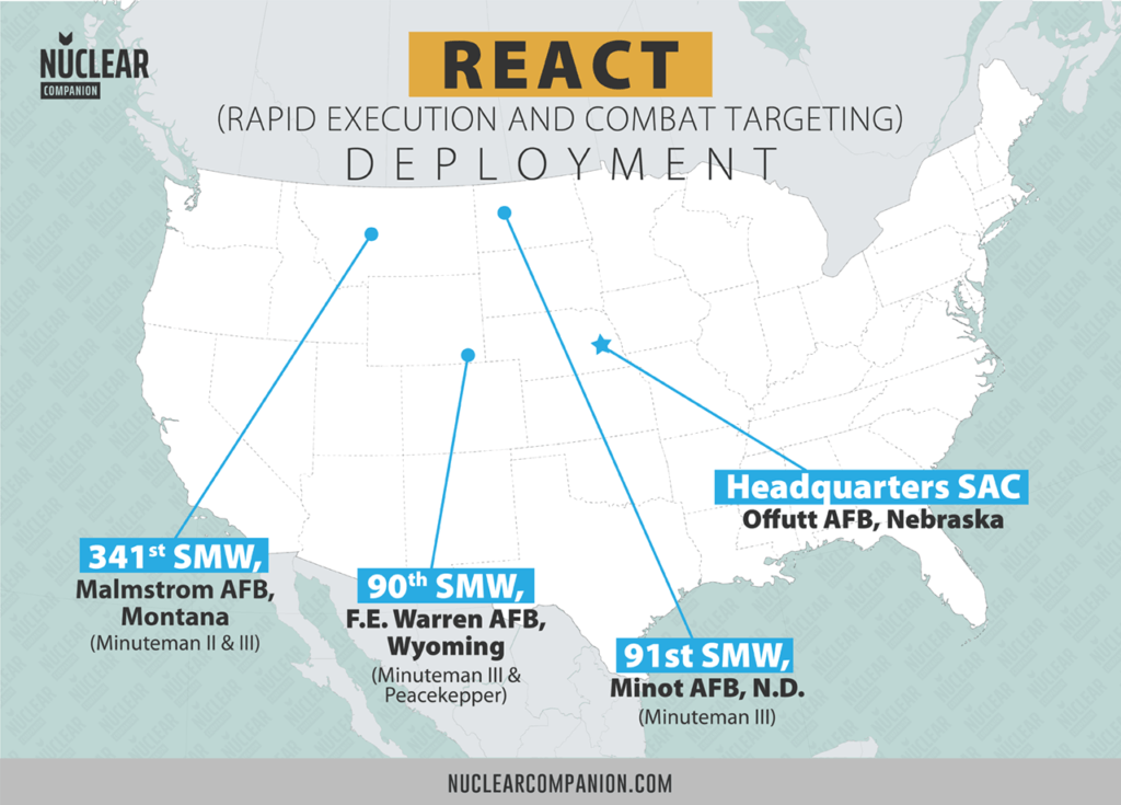
REACT equipment installed in a total of 50 Minuteman III Launch Control Centers at:
- F.E. Warren AFB, Wyoming
- Malmstrom AFB, Montana
- and Minot AFB, North Dakota
The first selected for the update was the 90th Missile Wing from Warren AFB. In Oct. of 1994, this wing completed the first Simulated Electronic Launch Minuteman (SELM) using REACT as part of Giant Pace 95-1M. It involved two REACT-modified LCCs from flights A and E of the 319th Missile Squadron.
Meanwhile, the 490th Missile Squadron became the first at Malmstrom AFB to deploy the REACT modifications. They began on March 1, 1995, and by August the Air Force had upgraded 27 of the 50 LCCs and 4 test facilities. As of Jan. 29, 1996, the Air Force had upgraded 7 more LCCs.
Subsequently, the final training class for the CDB/AM system graduated from Vandenberg AFB on Jan. 25. With it ended the CDM/AM training that took place there since 1975. All future Minuteman operations training transitioned to REACT system.
Finally, Full Operational Capability (FOC) was declared for RECT-A, Minuteman A/M LCCs, on July 31 1996. The initial Operational Capability (IOC) for REACT-B started on Aug 5, 1996. The first one was for the 564th Missile Squadron.
Program Updates
At the cost of 128 million dollars, the Rapid Execution and Combat Targeting (REACT) Service Life Extension (SLEP) was initiated in 2006. Hardware changes included upgrading the Embedded Memory Array Dynamic (EMAD) Card. Likewise, it upgraded the Visual Display Units (VDU) and the Head Disk Assembly (HDA).
For its part, the Console Operation Program (COP) software corrected its identified deficiencies. In 2008, REACT Console and Operator Input Device (OID) improved its interface. Above all, it improved its reliability and in-commission rate.
The cost of this improvement was 4,7 million dollars.
The REACT Console in detail
REACT vs CDB
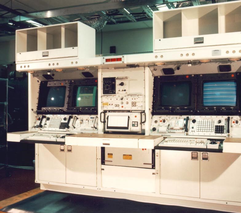
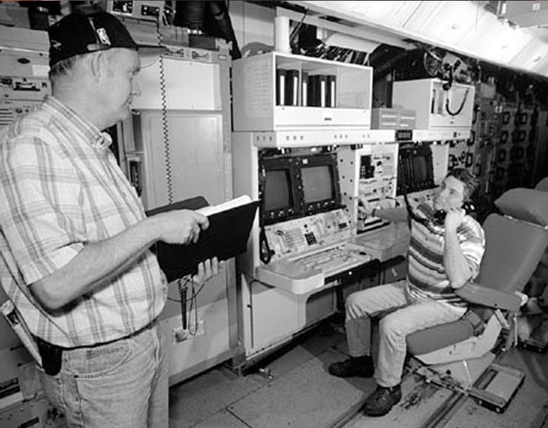
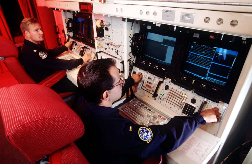
There is one stunning difference between REACT and the old Command Data Buffer (CDB). While the CDB had two separate workstations, in REACT both crews are side by side. In other words, they operate in a single console with a keyboard and trackball included.
One of the reasons behind this was to fit in the rail car of the defunct MX Rail Garrison. In the CDB, one workstation was for the Missile Combat Crew Commander (MCCC) and the other for the Deputy Missile Combat Crew Commander (DMCCC).
The REACT software uses Window’s-type screen displays that allow quick and reliable tracking of weapon system status and input of data.
Side note: Its software code is in ADA programming language.
Missileers can view the status of all 50 squadron missiles at the same time they display detailed status for their 10 primary sorties and the LCC. This provides much greater awareness of what’s going on in the entire squadron than CDB provided
However, the most important feature of the REACT is automation. This system receives war order messages through three digital communications channels:
- Very low-frequency radio
- The Air Force Satellite Communications System
- SAC digital information network
After authentication, sorting, and elimination of duplicates, the information appears automatically to operators. To give perspective, previously all these tasks were to be manually done. The documents for authenticating the codes, most importantly, remained in a double-locked safe.
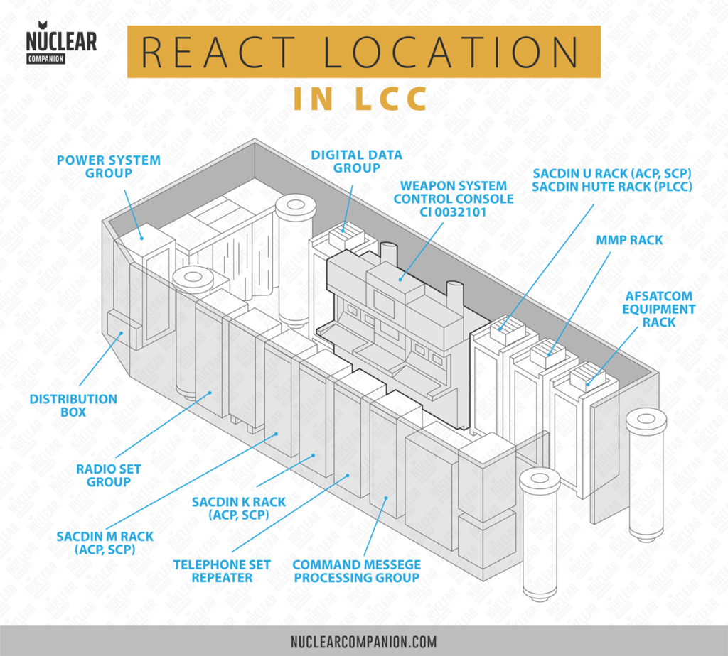
The old CDB system required the crew to run all over the LCC to react to and process EWO messages. Message traffic from higher headquarters was received over multiple communications systems and printed out on three separate racks that line one wall of the LCC. When traffic was received, one of the crew members just had to get up from his or her console to retrieve all of the message copies for the crew to use.
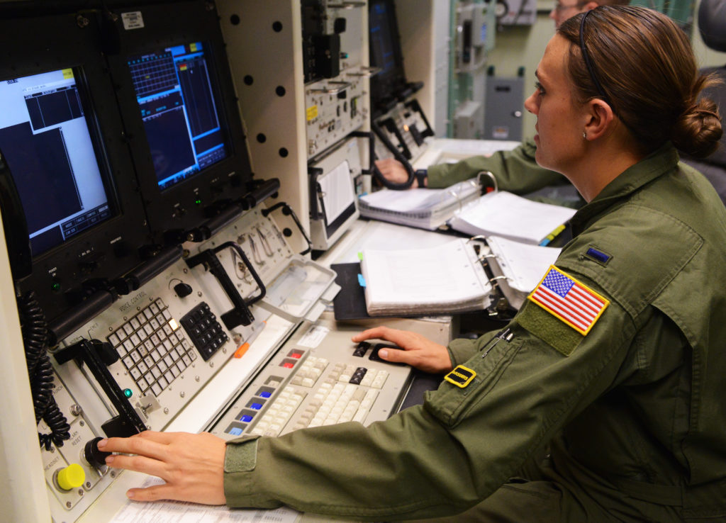
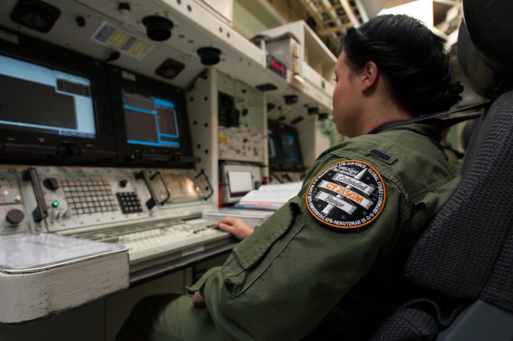
REACT integrates virtually all the critical tasks into a single console. That allows the combat crew to perform all their actions to go to war without ever having to get out of their chairs.
Regarding positioning, the Commander sits on the left workstation (left bay) while the Deputy sits on the right workstation (right bay). The shared equipment is located in the center bay.
Let’s break down REACT on its components:
REACT Mayor components
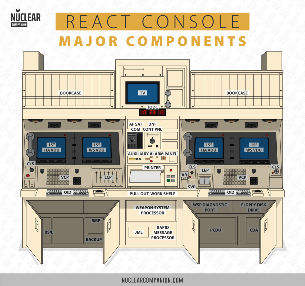
Visual Displays Units (VDUs)
These are 15-inch nuclear-hardened, high resolution, color, monitors. There are two per workstation. The left one is the HA VDU and the right is the WS VDU.
The Higher Authority Visual Displays Unit (HA VDU) is connected to the rapid message processor (RMP). It allows monitoring of HA communications.
On the other hand, Weapon System Visual Displays Unit (WS VDU) is connected to the weapon system processor (WSP). Interaction with the WS VDU display provides:
- Monitoring status of LCFs and LFs
- Initiating commands
- Performing remote targeting operations
- Other command and control functions
Rapid Message Processor (RMP)
The RMP enables the MCC to monitor and control the HA communications systems directly from the console. Outgoing messages can be composed, stored, and transmitted over multiple communications systems. Incoming messages are processed and displayed on the VDU. The RMP processes the following decoded messages:
- Emergency Action Messages (EAMs). These are launch execution orders.
- Force Direction Messages (FDMs). These are ICBM-targeting orders.
- Non-Action Messages (NAMs).
Also, the RMP signals the crew that a message has been received and, when commanded, displays the message. Duplicate messages received over more than one communications system are automatically eliminated. Communications alarms are also displayed.
Weapon System Processor (WSP)
The WSP is a general-purpose digital computer. More exactly, the Raytheon SMC 810. The function of the WSP is to control the flow of data within and through the LCC.
Operator-initiated messages are processed by the WSP, sent to the secure data unit for encryption, and returned to the WSP for transmission. Incoming LCC and LF messages received by the WSP are decrypted by the secure data unit, stored by the WSP, and processed for possible status display.
The WSP interrogates its designated LFs in a round-robin sequence. The WSP also controls and sequences target and execution plan calculations and remote data change operations.
Launch Enable Panel (LEP)
An unlock code together with a secure code in the launch enable control panel are required to enable missiles for launch. The unlock code for each missile would come through a launch order. This panel is part of the Deputy Commander’s workstation.
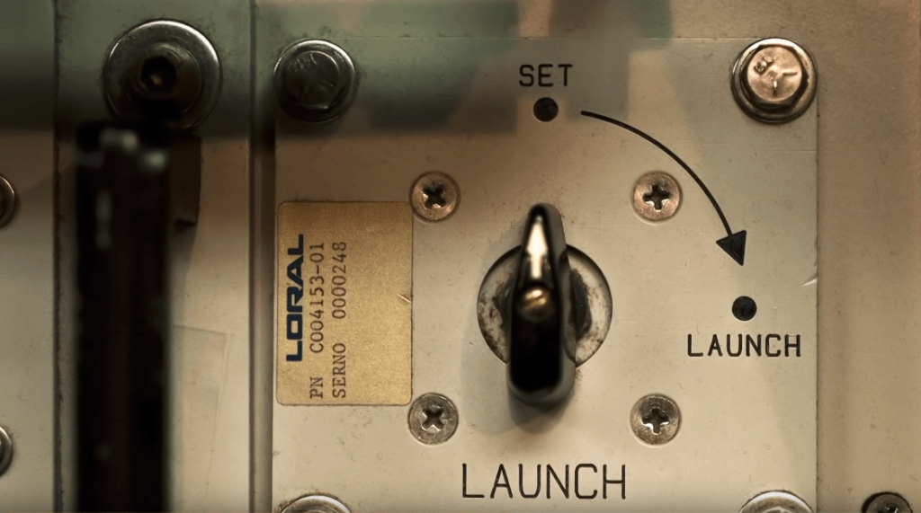
Launch Control Panel (LCP)
The LCP provides the initiating point for executing launch, inhibit, and test commands. Concurrent actuation of the Cooperative Launch Switches (CLSs) is necessary for the initiation of an executed launch command.
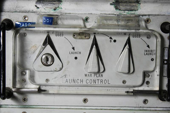
Cooperative Launch Switches (CLS)
The CLSs are used in conjunction with the LCP to provide two-person/four-hand operation during launch operations. Concurrent actuation of the three CLSs and the launch switch on the LCP is necessary for the initiation of an execute launch command.
Operator Input Devices (OIDs)
Each workstation OID provides the operator with an interface with the WSP or rapid message processor (RMP). The OID at each workstation can be connected to only one processor at a time (RMP or WSP) and one VDU.
Each OID is composed of a trackball assembly and a QWERTY keyboard with special functions.
Bulk Storage/Loader(BS/L) and Floppy Disk Drive (FDD)
The BS/L is a hard drive used for the initial load of the processor memory and for reloads in the event of a main memory upset or other fault causing a restart. It provides a secondary memory function for the weapon system programs and databases.
The FDD is used to provide removable read/write storage for non-critical WSP functions. The FDD is also used to download diagnostic data and archive the crew log on a periodic basis. Floppy disks may be used to reload the targeting and other data files and to transfer data files from one LCC to another.
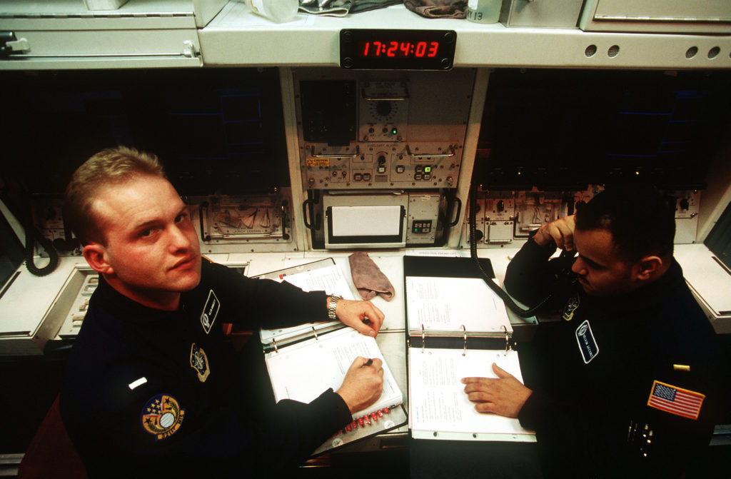
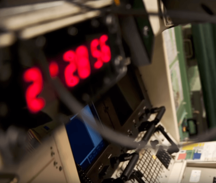
Time-of-Day Clock (TODC)
The TODC is located in the upper center bay of the console. It provides a time-of-day display viewable by either operator. The TODC displays the time in military format is accurate to at least one second within a 24-hour period and will remain functional during the loss of primary power.
But, how do we launch a Minuteman Missile with REACT?
The Enable and Launch codes
Before the launch sequence, the missile must be in a “Strategic Alert” status. That is, the missile is in launch readiness mode. On the contrary, the missile’s nonoperational status is called “No-go”
To successfully launch a Minuteman missile two codes are needed: the enable and launch codes.
Each missile stores these codes, which allow them to operate if called upon at a moment’s notice. A part of these codes is in a Hard drive (software) and the other part is in the permutation plug, or P-plug (Hardware). An EMT team (an electromechanical maintenance team) changes these codes every year.
First, we need to enable or unlock the missile. For this purpose, the enable code is used.
Part of this code is stored in the Mechanical Code Units (MCUs) of the LEP. Another part, the unlock code, is received in an Emergency Action Message.
This design is called “split-knowledge”. No single individual can have access to, or the ability to transmit, the entire code.
Side note: Prior to 1977 each LCC had the entire enable code.
If the transmitted values equaled the stored values at the missile, then the missile would report back that it was enabled.
Then, we can launch the missile. In the case of the launch code, the LCP stores it in its MCUs. The WSP transmits it when the combat crew activates the LCP and the Cooperative Launch Switches.
The Minuteman III launch procedure
Side note: This is our guess of the procedure. It is based on unclassified information found on the internet. The detailed and complete procedure for obvious reasons is classified.
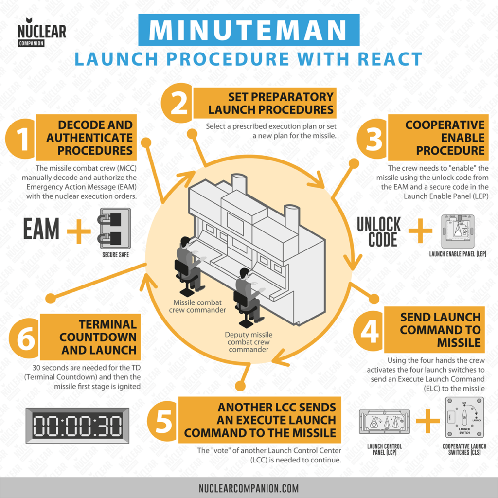
1- Decode and authenticate incoming EAMs
The RMP signals the crew that a message has been received. A visual EAM alarm is generated together with an audible alarm. These EAMs are manually decoded and authorized by the MCCM.
The EAM may contain:
- Execution plan number
- Target number (index from the SIOP(Single Integrated Operational Plan))
- Timing plan (to prevent aircraft and missile fratricide)
- Retargeting modes (CEP/MRT).
- Enable codes (Unlock codes)
- Authorization codes known as sealed authentication codes (SAS codes)
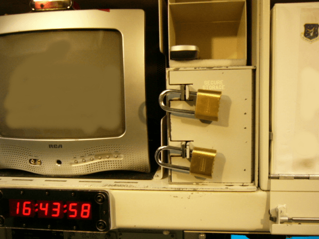
In order to authenticate the message, the crew compares the SAS codes with codes stored in a dual-lock secure safe. If they matched, it indicated a valid direct command from HA.
Also, inside the safe, there are two launch keys, which look like car keys.
2- Set preparatory launch procedures
Then, if necessary the missile combat crew can send commands to all missiles in the squadron to select a prescribed execution plan. Or send commands to establish a new war plan data to a specific missile or the entire squadron:
- Target number and execution plan number
- Missile launch delay time
- CEP/MRT mode
Re-targeting times depend on whether the re-targeting mode is Minimum Reaction Time (MRT) or Circular Error Probable (CEP). In the very fast MRT mode, the new target and the old target both lie within a certain small azimuth angle from the launch point, and the missile can perform its realignment after launch mainly by adjusting the elevation angle of the missile’s trajectory.
In the CEP mode, the new target lies outside the azimuth flexibility of a missile aimed at the old target, and the missile must, therefore, realign its guidance platform prior to launch. This CEP realignment would typically take between 15 and 30 minutes to complete.
3- Cooperative enable procedure
Before using the missile, we need to enable it. For that purpose, the crew of the LCC must send an “Enable Command” (ENC) to the missile.
First, the Unlock code is entered into the system. And then, the LEP switch is set to enable.
The system generates six random alphabetic characters using some variables and the Unlock Code. Half of the characters are displayed on each workstation VDU, and the operator at each workstation must enter his/her three characters correctly from the keyboard when the data entry appears. This must be accomplished within a determined amount of time.
The missile now is “enabled” waiting for an Execute Launch Command (ELC). But, it can be “disenabled” with an Inhibit command sent to the missile by any LCC.
4- Send Launch Command to Missile
Now, we can send a Launch Command to the missile.
The command is initiated at the LCP in cooperation with the three cooperative launch switches and contains the secure code extracted from MCUs in the LCP.
Because the two MCCMs are side-by-side, there is a trick to avoid launchings by a single person.
Indeed, the ELC (Execute Launch Command) requires a cooperative effort from both combat crew members in that the launch switch on the LCP and the three coop launch switches must be activated within 2 seconds of each other.
After processing the command, now the missile is in a “Launch commanded” state. Again, it can be inhibited with an Inhibit command sent to the missile by any LCC.
5- We need the vote of another LCC
In order to get into a “Launch in Progress” status, the missile needs the ELC of another LCC.
What happens if no other LCC is up? For example, 4 of 5 of the LCCs of the squadron have been destroyed by a nuclear attack. In that case, after a timer runs out the missile will go into “Launch in Progress”.
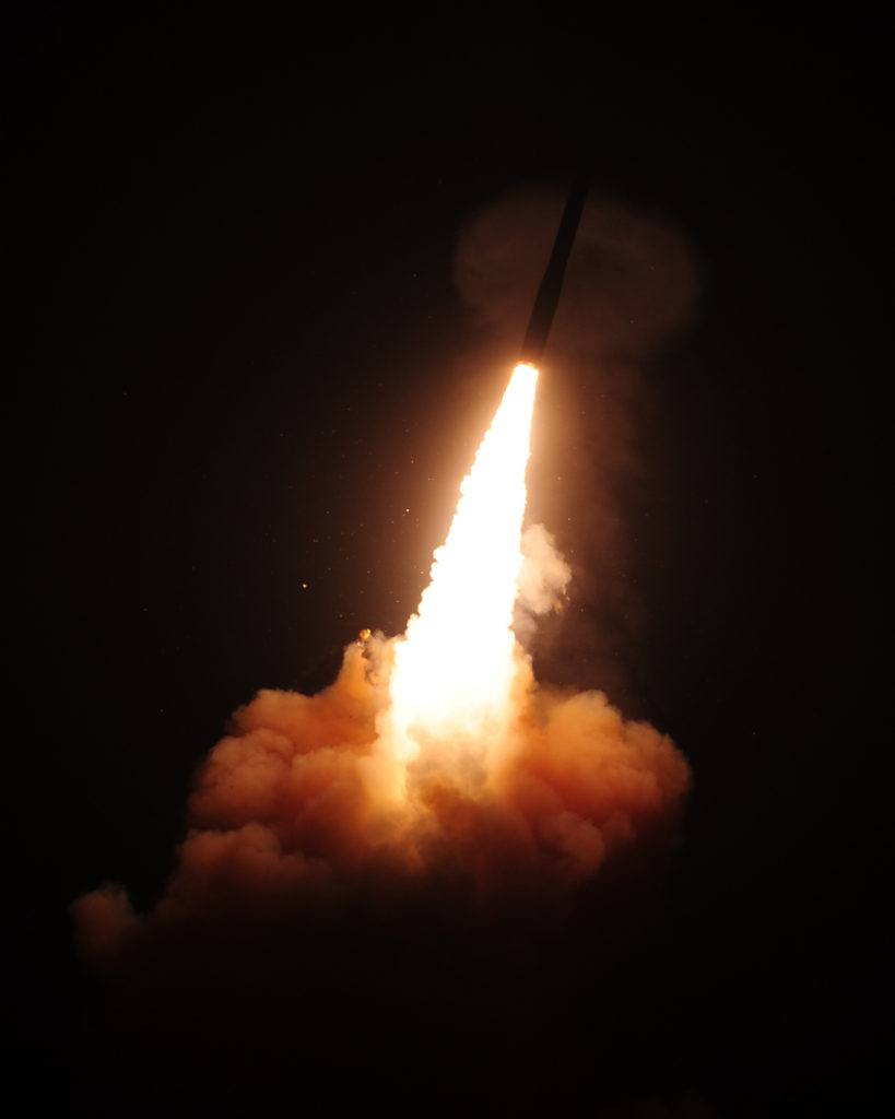
6 – Terminal Countdown (TCD) and missile launch
You can see a YouTube video with some parts of the launch procedure:
Emergency Action Messages (EAMs)
According to “Bulletin of the Atomic Scientists, Dic. 1986”, each EAM is identified by three numbers; the 200 series is reserved, for instance, for transmitting official changes in alert levels. The most critical EAMs are designated “nuclear control orders.”
According to a partially declassified JCS manual on nuclear control orders, there are 11 distinct “nuclear execution messages” and six “nuclear termination messages.”
An example of a nuclear execution message is one entitled “Selective Release of Nuclear Weapons.” A “Red Rocket” message would be used to implement the “fast reaction procedures” if the United States were under sneak attack.
Conclusion
At the end of the Cold War, the U.S. Air Force started an upgrade to its Launch Control Centers consoles. It took its 1960s and 1970s technology to the 1990s. Indeed, REACT proved to be vastly more effective and efficient than its predecessors.
For today’s standards perhaps it is an old technology but it has an advantage: Security. Old hardware and software, and the lack of an Internet connection provide solid security for the launch centers.
Now It’s Your Turn
And now I’d like to hear from you:
Or maybe you have a question about something you read.
Either way, go ahead and leave a comment below with your thoughts.
Thanks for this Documentation. As a Non-Expert now i can understand how this mighty system works.
What is correct: The 12″ FDD were integrated the first Time in the early 70’s or by Rollout of REACT Console in the 90’s?
Greetings,
Tom
8 in floppy disk drive wS standard equipment on HUTe of SACdin Terminal in mLCC dwritten at HQ Sacsaccs SoftwRe Test Facility and distributed to wing level Topsecret Control for DistributionMLCC Base Communication BCP node of Sacdin for routing and Network Configuration NO hard drive In SacDin. THINK OF IT LIKE A COMPUTER DESIGNED TO BOOT OFF 8 inch Floppy like Wargames movie Imsai computer. Exact identical Disk Media
Sry i mean 8″ FDD
Hi Tom. Launch Control centers incorporated 8″ FDD in the 90s with REACT Console. The older system, Command Data Buffer(CDB), was from the beginning of the 1970s and didn’t have any floppy disk at all. The Legacy 8″ FDD was later replaced by moderns ones.
Hello Paul, thank you for your answer, now that’s clear for me. Hope that someday i can visit D01/D09 (;-) Best Regards
Tom/Germany
That Minuteman visit is a must! I will publish a guide for touring it this year. For the moment, very busy writing about Operation Crossroads. Thanks to you!
I wish you success with your “Operation Crossroads Project”!!! – A Tour Guide – that will be fine!
What happens if no other LCC is up? For example, 4 of 5 of the LCCs of the squadron have been destroyed by a nuclear attack. In that case, after a timer runs out the missile will go into “Launch in Progress”.
This makes it sound like the vote of another LCC does not matter because once the timer stops the launch will proceed.
Hi Scott.
It does matter. Once an LCC sends its ELC, a second LCC can:
1) send the second ELC vote, thus approving the launch and after that the terminal countdown initiates.
2) send an Inhibit Command (The missile enters in an inhibited mode and it will return to the disenabled state after 5 minutes if no additional
ELC vote is received) or
3) wait for the first ELC timer to run out (initiating terminal countdown). Not sure how many minutes or hours it takes.
So, if an LCC goes rogue, a second LCC can make the difference by inhibiting the launch.
Hi Paul. I am a veteran of CDB and ILCS in the early 80’s. With the RMP I would probably be lost today not having the ingrained automatic response to the warble tone to grab the classified to decode FDM/EAM traffic. That warble is a sound that will forever haunt and put me in combat mode. A couple commments/questions:
First, the LCP and LECP are very familiar. Beneath the DMCCC Left CLS is a panel labeled SVP which is not familiar to my history in the older systems. What is the SVP?
In the CDB/ILCS consoles, the MCCC launch key was integral to the LCP and appears to still be. However, the DMCCC launch key was in a command processing rack to the left of the DMCC console in ILCS and in the DMCC right surface for the Sylvania CDB system. Where is the DMCCC key with React… it is not apparent in the pictures.
Second, it is important to note that the HAP and WSP are exclusive. The link between receiving a Launch Order and the Execution of the Launch is a manual human process. There is no electronic link by which the HAP can initiate or inhibit a launch.
Hi Tim,
Thanks for sharing! I hope someday I can write an article about CDB and ILCS. No much public or unclassified information about them for the moment.
The SVP is the Safe Voice Panel. I believe it contains some mechanical code to encrypt/decrypt voice communication.
Regarding the DMCCC launch key, I think there is no such key. You’re right about the pictures. The DMCCC has to concurrently actuate 2 of the 3 CLSs while the MCCC has to actuate 1 CLS and 1 Launch Switch (in the LCP) using the Launch key stored in the secure safe of the center bay.
I will update the article with this info and the HAP and WSP link. Thanks!
Do you know if the “used” positions on the launch and inhibit switches are just visual indications, or is there a
mechanism to prevent second and subsequent uses. e.g. If a single missile is enabled and launched, can the
LCCs that participated in that launch, participate in subsequent launches or is their LCP spent?
Hi Bill, thanks for commenting. When these switches are used, they will only return to the “Code Used” position. Not sure how the crew reset them to a prelaunch position but the LCC can participate in additional launches and inhibits.
Paul, once the keys have been inserted and turned, they cannot be physically removed (by the crew) and the Launch Switch will indicate Code Used (as you noted). Once keys have been installed and used, as you said, subsequent keyturns can be accomplished. Crews can NOT reset these switches/keys themselves–the panels would have to be removed from the LCC (and replaced with new panels), returned to the support base, and reset/recoded by code controllers in a Top Secret vault where coding operations are conducted. Hope this helps.
Great article-
I have a few questions:
1. Did the RV’s in all versions of the Minuteman contain a Permissive Action Links (PAL).
2. If so, did the PAL have to be programmed locally at the warhead bus or could it be done remotely at the REACT console in later versions.
Thanks
Hi Matt,
PAL was used on most bombs and air-to-surface missiles together with a nuclear-capable aircraft cockpit fitted with an Aircraft Monitoring and Control(AMAC) System.
For Intercontinental Ballistics Missiles, dual LLCs were used and for ballistics submarines, redundant locks.
Hi all – old thread I know, but if that video is indicative of the EWO Launch Checklist that crew would never have made the commit time for SIOP 5. I’m an old CDB MCCC (crew E013, 740SMS/91SMW, Minot.). I realize things change but that setup looks like a shi+ show – I’ll take my old CDB LCC anyday. Errors in your article – where to start. I’ll start with the easiest. The CDB capsule never required either the MCCC or DMCCC to unstrap and leave thier seats for the receipt of hardcopy comm messages. The DMCCC could get the SACCS and SLFCS/SATCOM hard copy without even sliding the seat on it’s rails. Second, and not your fault, the design of that POS console means a REACT crew could never stay with a CDB crew speed wise – my crew would have dusted those two O5’s without even trying. From what I can see the old MSIP allowed for situational awareness that was exponentially better than REACT. Now I know people are gonna say it’s just some old fart talking about how much better it was in the ol’ days but that capsule configuration may have been a step forward for EWO flexibility but it was a giant step backwards for the crews.
Hi Gary! Thanks for sharing your firsthand experience as a former CDB MCCC. I apologize for any inaccuracies in the article, and I appreciate your input. It’s important to consider how systems and protocols change over time, and your perspective adds valuable insights to the discussion. If you have more feedback, please feel free to share. We’re always eager to learn and improve our content.
Correction on the P-Plug. It is not handled by the Electromagnetic Team, but the Missile Mechanical Team (MMT). There is a separation of knowledge for maintenance personnel. “A” side is the P-Plug, which is installed into the missile guidance unit when it is installed on the missile. MMT handles the hardware on the missile. EMT handles the “B” side software which they install into the racks in the Launch Facility. This is from my days as a maintenance officer in the mid-80s.
LCP and LECP still operate the same as in ILCS or CDB – with exception that LECP ditched the 6 thumbwheel entry in favor of a split 3+3 input from each MCCC and DMCCC. In ILCS and CDB the LECP did not communicate with the missile; it merely enabled LCP in the that LCC; I don’t believe REACT changed that. Over time, the LECP enable code was located in various places, the LCC Safe in a sealed pouch, the WCP, HQSAC. It was never 00000000 as is widely claimed… for one thing it only had 6 dials, and they were limited alpha-numeric. The WSP is basically bypassed by the LCP (other than SSAS type link encryption). The WSP’s role is primarily in the maintenance adn configuration of the missile including targeting and selection – not the launch. Both LCP and LECP incorporate the same original WS-133AM electro-mechanical devices (sealed code canisters)… basically the underlying LCP and LECP launch mechanism remains unchanged.
Sole survivor launch procedures are more complicated than a ‘dead man’ timer expiring. I’ll leave it at that… and then there is ALCS too.
Great article! In the REACT console we see a number of different status codes. Does anyone know what they mean or know of any other status codes? So far I have these:
TGCH: Targeting Guidance Computer HW (according to ChatGPT). What does it mean?
ALGN: Alignment (?). What does it mean?
LIP: Launch in Process (not shown but according to Popular Mechanic it is there somewhere).
ELC: Enable Launch Code (launch is authenticated by the missile and is waiting for a second vote).
CES: Commited Executed Sortie (missile is on its way).
Thanks Patrick!
ALGN probably makes references to the method of aligning the guidance system correctly in the horizontal plane, a process that, though it took place before launch, was as crucial to accuracy as anything that happened in flight.
Not sure about TGCH.
Just noticed that there are two “Tim Christensen” . Indeed we are two different individuals. He was a MCCC, I was in Maintenance Both of us are legit.
Hi Tim, Thanks for sharing your experience maintaining these systems.
How would modern warfare tactics and strategies be impacted if we were forced to rely on outdated technology like floppy disks and trackballs in a high-stakes combat situation?”,
“refusal
Seems like the old REACT system is getting an upgrade as well with the new LGM35-sentinel program. From what I can gather from the picture, the four horizontally stacked 15″ VDUs are replaced by two big and two smaller screens where the smaller screens shows the ICBM squadron status and the big screens shows everything else. Looks pretty cool. The twin padlocked safe is still there and so are the four hands CLS/LCP switches.
https://www.northropgrumman.com/space/sentinel
Hope you can cover the new upgrade when more information is available.