Introduction
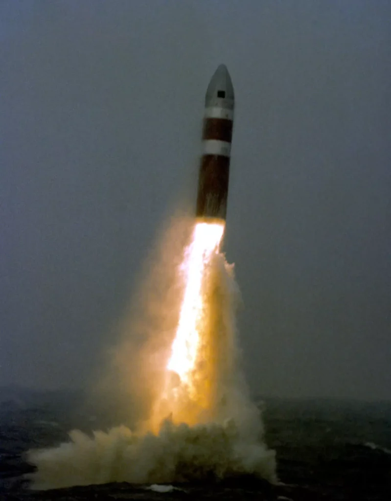
The Poseidon C3 missile was a solid-propellant, two-stage, intermediate-range ballistic missile, notable for its maneuverable equipment section designed to deliver reentry bodies (RBs) to single or multiple targets. It could be launched from a fleet ballistic missile submarine, either surfaced or submerged.
Larger and more sophisticated than its predecessor, the Polaris missile, the Poseidon featured advanced electronics, resulting in a highly accurate guidance system. It had a longer range and could support four different multiple reentry body configurations, offering a broader range of target options.
While similar to Polaris as a two-stage missile, Poseidon uniquely included a third stage—the equipment section—capable of powered flight. This section housed a gas generator and eight thruster valves, providing omnidirectional maneuverability, which was crucial for delivering its multiple RBs to varied targets. The gas generator also enhanced the missile’s range by adding downrange distance.
Weapon System
Before going deeper into the details of the Poseidon missile, it’s important first to understand the functioning of the Poseidon Fleet Ballistic Missile (FBM) Weapon System as a whole.
The Poseidon Fleet Ballistic Missile (FBM) weapon system encompassed more than just the Poseidon missile. It included several integral subsystems:
- Ship System (616, 627 & 640 Class): This served as a mobile base for the FBM weapon system, providing essential services for maintaining and launching the missile. These services included electrical, pneumatic, and hydraulic power, environmental monitoring and control, hovering and compensation, and internal communications.
- Mk 2 Ships Inertial Navigation System (SINS) Mod 6: Constantly monitoring the submarine’s location (longitude and latitude) and attitude (pitch, yaw, and roll), this system transmitted data to the fire control system for computing missile trajectory and programming the missile guidance electronics assembly.
- Mk 6 Missile Test and Readiness Equipment (MTRE): It was responsible for preparing and checking the missiles, MTRE assessed readiness conditions for launch.
- Mk 88 Mod 1 Fire Control System: Acting as the nerve center, it monitored all systems and managed data essential for a POSEIDON missile’s successful launch and flight. It controlled all systems during a launch sequence.
- Mk 24 Missile Launcher System: It provided the mechanism for ejecting the missile from the submarine, protecting it from shock and vibration while aboard.
- Integrated Data Acquisition Subsystem (IDAS): A non-tactical subsystem, IDAS processed and recorded FBM weapon system performance data during test programs.
Together, these subsystems enabled the effective operation and management of the Poseidon FBM, ensuring its readiness and precision in launch and flight.
Physical description
The Poseidon C3 missile, designed for launch from fleet ballistic missile submarines, weighed approximately 65,000 pounds (29.484 kg) and measured around 34 feet (10,36 m) in length. Its diameter was 74 inches (1,88 m) at the base, tapering to 72 inches (1,83 m) at the equipment section.
With a range of 500 nautical miles (926 km) to 3,000 nautical miles (5.556 km), the Poseidon C3 significantly surpassed its predecessor, the Polaris missile, in operational reach and accuracy, boasting a Circular Error Probability (CEP) of 450 meters. It had a declared throw weight of 3,300 pounds (1.497 kg).
A key feature of the Poseidon C3 was its Post Boost Vehicle (PBV), which could carry up to 14 Reentry Vehicles (RVs), though typically it carried 10 as per START treaty declarations.
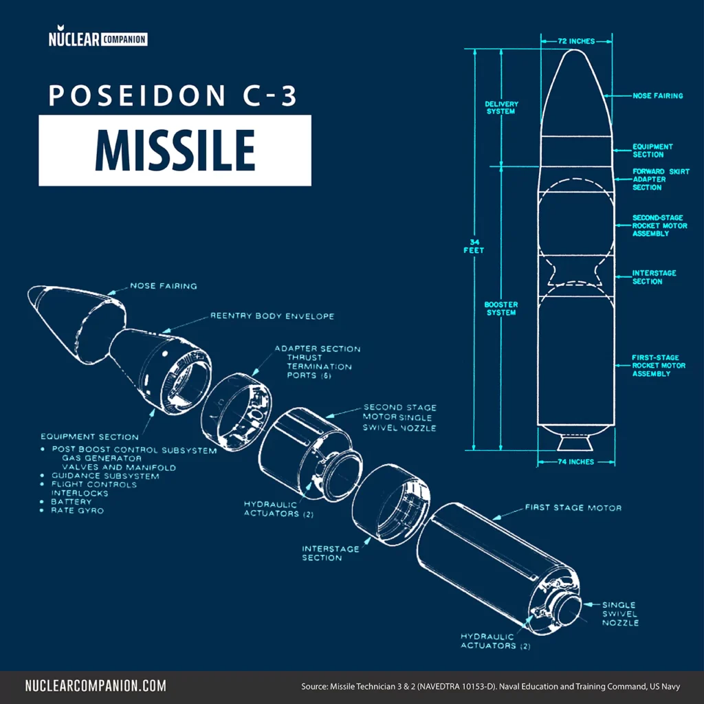
The Poseidon C3’s flight was divided into boost and deployment phases. Correspondingly, the missile was split into booster and delivery systems.
The booster system, responsible for controlled thrust during first- and second-stage powered flight, included a first-stage motor assembly, interstage section, second-stage motor assembly, and forward skirt adapter section.
The delivery system, crucial for precise attitude and velocity during Reentry Body deployment in the deployment phase, comprised an equipment section, nose fairing, and reentry subsystem, with the latter enclosed within the nose fairing.
First Stage
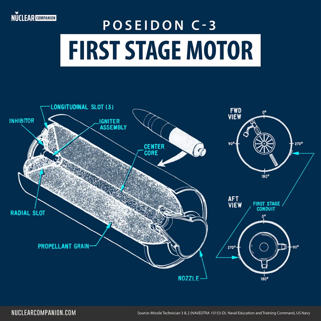
The first-stage rocket motor of the Poseidon missile was responsible for the initial acceleration during the boost phase. Explosive impulses from the ordnance subsystem triggered the ignition of both the first and second-stage motors.
The propulsion for the C3 was developed by a joint venture between Thiokol Chemical Corporation and Hercules Inc. Specifically, Hercules Inc., based in Bacchus, Utah, developed and produced the first stage, while Thiokol supplied the propellant.
The following table displays the First Stage Motor’s general characteristics:
| Attribute | Value |
|---|---|
| Chamber material (Fiber) | S-901 Fiberglass |
| Chamber Composite Stress Level (Psi) | 110,000 lbs / 49,895 kg |
| Chamber Maximum Operating Pressure (Psi) | 920 lbs / 417 kg |
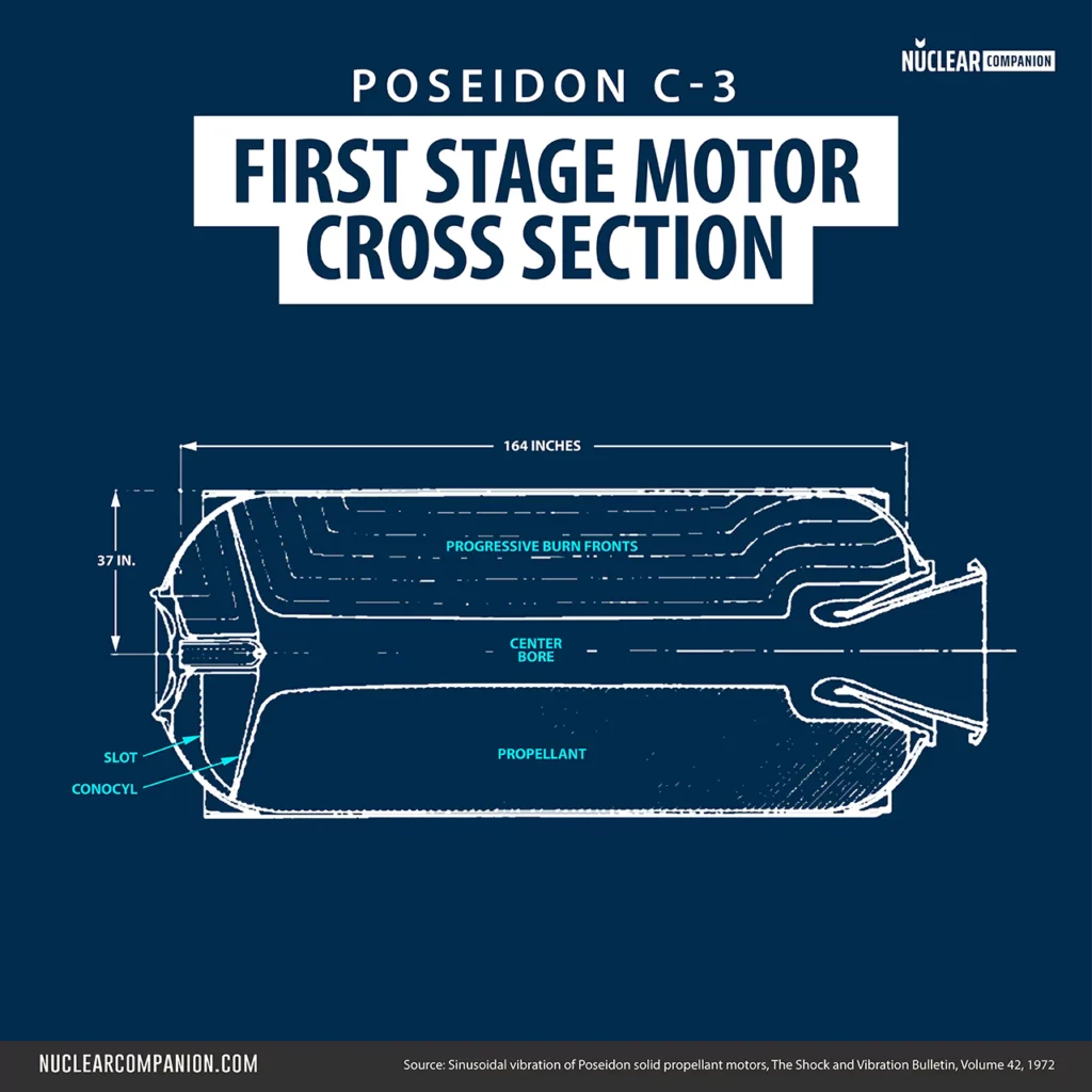
| Chamber Skirt/skirt Length | 157 in / 399 cm |
| Chamber Diameter | 74 in / 188 cm |
| Nozzles Number | 1 |
| Nozzle Throat Mail | Graphite phenolic |
| Thrust vector control (TVC) | Flex joint |
| Nozzle Type | (steel reinforcements) graphite, carbon asbestos phenolic |
| Nozzle Weight (Each) | 765 lbs / 347 kg |
| Chamber/insul Weight | 2,156 lbs / 978 kg |
| Propellant Weight | 38,800 lbs / 17,599 kg |
| Total Weight | 41,860 Lbs / 18,987 kg |
Chamber
The first-stage chamber of the Poseidon missile, like the Polaris A3, utilized chambers made of Spiralloy, a fusion of fiberglass and epoxy resin.
This technology originated in 1956 when Young Development Laboratories developed a method to wrap epoxy resin-soaked fiberglass threads around a phenolic asbestos liner. The resulting Spiralloy shell, after curing, offered a strength-to-weight ratio 20 percent higher than stainless steel.
Propellant
The Poseidon First Stage used a composite propellant designated TP-H1123 that used Polybutadiene acrylonitrile (PBAN) as a binder (14%), Aluminum (16%) as fuel, and Ammonium perchlorate (69.60%) as an oxidizer. Similar formulas were used for the first stages of Minuteman, Titan III, and the Space Shuttle’s solid rocket boosters.
Trust vector control
The first-stage thrust vector control of the Poseidon C3 missile marked a departure from Polaris missile designs, which usually had four nozzles per stage.
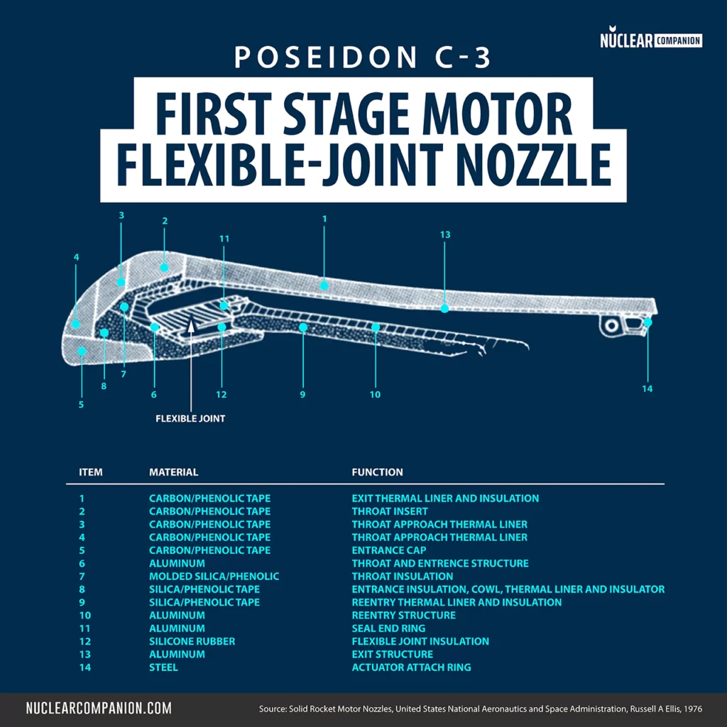
Instead, the C3 employed a single movable nozzle for each stage. These stages featured a flexible-joint movable-nozzle system equipped with a graphite/phenolic throat insert.
This flexible-joint system used the flex seal concept for thrust vector control, involving alternating layers of reinforcement and elastomer. This movable nozzle was controlled through hydraulic pistons, pressurized by gas generators, allowing precise directional control of the missile during flight.
Interstage Section
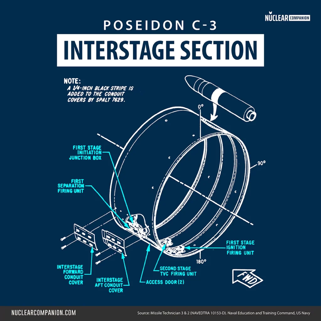
The interstage section of the Poseidon missile connected the first and second-stage motors, supporting and safeguarding internal components.
Made from hardened aluminum alloy, it weighed about 195 pounds (88,4 kg), measured 34 inches (86,3 cm) in length, and had a 74-inch (1,88 m) diameter. Two access doors at 45- and 225-degree positions enabled component access when the missile was assembled.
Air bleed holes in the section allowed for pressure equalization. When mated to the motors, these access doors also provided entry to components on the first-stage motor’s forward end and the second-stage motor’s aft end.
Second Stage

The second stage of the Poseidon C3 missile accelerated the missile’s post-first-stage separation and led into the deployment phase. This stage ignited simultaneously with the detachment of the first stage, triggered when missile acceleration reached a predetermined value.
The guidance system determined the end of the second-stage flight, achieved by opening six thrust termination ports to create reverse thrust, thereby halting acceleration.
Like the first stage, the second stage of the Poseidon was developed and produced by Hercules, Inc. in Bacchus, Utah.
The following table displays the Second Stage Motor’s general characteristics:
| Attribute | Value |
|---|---|
| Chamber material (Fiber) | S-901 Fiberglass |
| Chamber Composite Stress Level (Psi) | 120,000 lbs / 54431 kg |
| Chamber Maximum Operating Pressure (Psi) | 410 lbs / 186 kg |
| Chamber Skirt/skirt Length (In) | 59 in / 150 cm |
| Chamber Diameter (In) | 74 in / 188 cm |
| Nozzles Number | 1 |
| Nozzle Throat Mail | Graphite phenolic |
| Thrust vector control (TVC) | Flex joint |
| Nozzle Type | (steel reinforcements) graphite, asbestos phenolic |
| Nozzle Weight (Each) | 425 lbs / 193 kg |
| Chamber/insul Weight | 720 lbs / 327 kg |
| Proppellant Weight | 15,880 lbs / 7203 kg |
| Total Weight | 17,115 lbs / 7763 kg |
Propellant
The second stage of the Poseidon C3 missile utilized a Composite-modified double-base (CMDB) propellant, a hybrid of double-base and composite propellants.
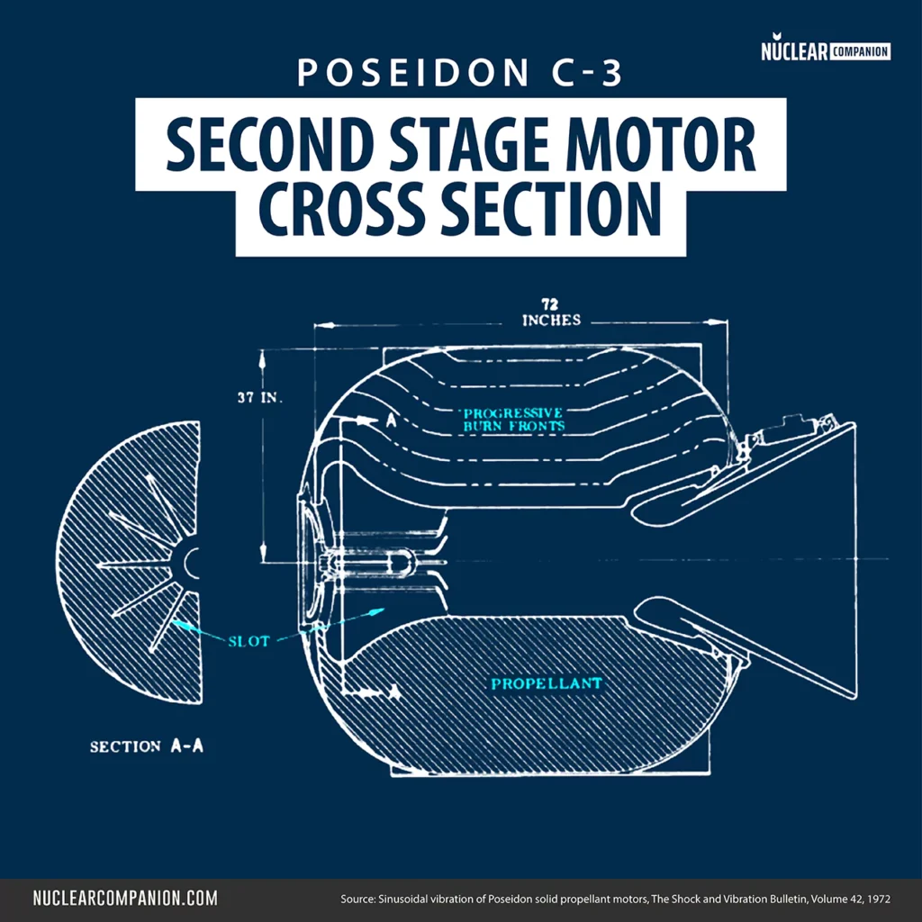
Its composition included a double base binder (nitrocellulose and nitroglycerine), an oxidizer (Ammonium Perchlorate, AP, plus HMX or RDX), and powdered aluminum as fuel. Additives improved bonding and burning.
The inclusion of an energetic nitramine, such as HMX or RDX, enhanced performance, increased density, and produced a non-smoky exhaust. This CMDB formulation was typically represented as AP-HMX/NC-NG/AL.
Forward Skirt
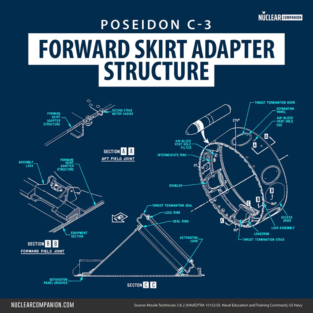
The forward skirt of the Poseidon C3 missile connected the second-stage motor to the equipment section, offering support and protection for internal components.
Constructed from hardened aluminum alloy, it weighed about 217 pounds (98,4 kg), was 24 inches (61 cm) long, and had a diameter of 74 inches (1,88 m) at the aft end, tapering to 72 inches (1,83 m) at the forward end. It featured six thrust termination stacks and doors spaced evenly around its circumference.
An access door at the 180-degree position allowed access to the forward skirt and equipment section components, as well as to the second-stage motor dome. Air-bleed vent holes in the skirt equalized internal and external pressure during various flight stages.
Equipment Section
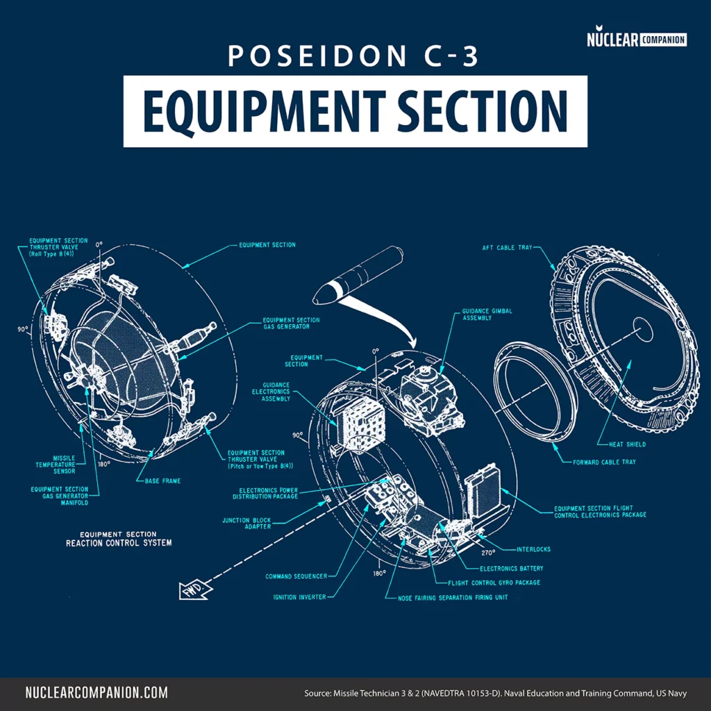
The equipment section of the Poseidon C3 missile connected the nose fairing and forward skirt adapter, supporting and protecting internal equipment.
Made of hardened aluminum alloy, it weighed about 195 pounds(84.4 kg), measured 25.5 inches (64.7 cm) in length, and had a 72-inch diameter (1,83 m). The section featured air-bleed vent holes for pressure equalization during various flight phases and has cutouts for antennas, used in evaluation or test missions.
While lacking access doors, the forward skirt adapter’s door provided necessary access. It included an optical window for guidance alignment and a base frame with support rings for mounting reentry bodies (RBs).
Guidance Subsystem
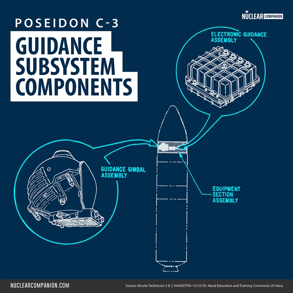
The Mk 3 Guidance System for the Poseidon C3 missile provided a stable flight reference, stored prelaunch data, processed in-flight data, offered attitude reference signals, and issued commands for flight control, including velocity-to-be-gained calculations for cutoff and Reentry Bodies (RBs) releases.
Developed by MIT’s Instrumentation Laboratory, with work distributed among General Electric, Raytheon, Bendix, and Honeywell, the system was designed to withstand nuclear radiation effects, addressing concerns raised by the Soviet Galosh system.
It comprised an inertial measuring unit and an electronics assembly with a digital computer:
Guidance Gimbal Assembly
The Gimbal Assembly included three 16-size (1.6-inch diameter) Pulsed Integrating Pendulous Accelerometers (PIPAs) and three 25-size Mod. 3 Inertial Reference Integrating Gyroscopes (IRIGs). These components allowed an accurate measurement of acceleration and angular velocity.
Evolving from earlier designs, these components feature significant improvements in accuracy, with the PIPAs notably enhanced by reducing bias and scale factor errors through permanent magnet torques and an updated torquing method. These advancements were developed at the Instrumentation Laboratory and enhanced performance by ‘more than an order of magnitude’.
Electronic Guidance Assembly
The Mk 3 Guidance System’s Electronic Assembly featured small-scale integration (SSI) circuits with approximately 5000 gates, a significant increase from 400 in Mk 1 and 800 in Mk 2.
It included 100K of read-only memory (ROM) for permanent program storage like guidance formulations and 12K of plated wire random-access memory (RAM) for pre-flight and in-flight variables.
The plated wire memory, chosen for its radiation-hardened properties, was essential for the system’s reliability in nuclear environments.
Reentry Subsystem
The reentry subsystem of the Poseidon C-3 missile consisted of several Mk 3 Mod 0 reentry bodies (the naval terminology for reentry vehicles).
These reentry bodies were fixed onto support rings that connected to the missile’s base frame. These rings also contained mechanisms for separating and ejecting the reentry bodies.
Cables linked the reentry bodies with the missile’s electrical system. During the deployment phase of the flight of the missile, the equipment section maneuvered to deploy each reentry body.
| Payload (RVs) | Max Range | Crossrange |
|---|---|---|
| 6 | 3,000 nm / 5,556 km | 300 nm / 555 km |
| 10 | 2,500 nm / 4,630 km | 150 nm / 278 km |
| 14 | 1,800 nm / 3,333 km | ?? |
Each Mk 3 reentry body carried a W68 40-to-50-kiloton nuclear warhead from the Lawrence Livermore Laboratory. The Mk 3 had a beryllium heat shield and a graphite nose-tip, and it was hardened to resist anti-ballistic missile systems.
Reentry bodies deployment
Prior to launch, the missile’s electrical subsystem, in coordination with the Mk 88 fire control system, fused each reentry body within the reentry subsystem of the Poseidon C3 missile.
During the second-stage flight, the equipment section received a boost to a specific point in space, enabling the first RB to free-fall towards its target. This section then moved away from the burning second-stage motor to the release point.
In the deployment phase, the equipment section’s reaction-control system, comprising a gas generator and eight thruster valves, maneuvered the loaded section for each RB deployment. This system allowed omnidirectional translational maneuverability, essential for precise positioning.
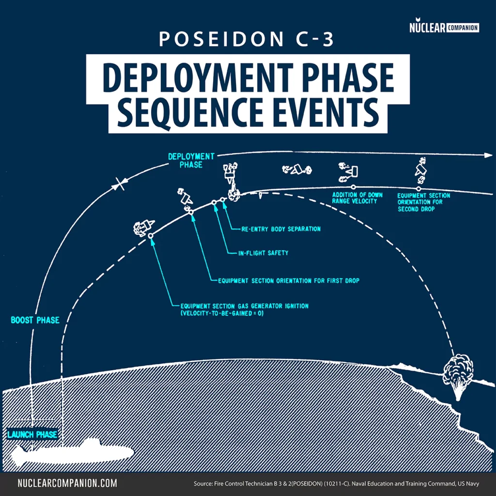
After each RB release, the flight-control subsystem sent a reset signal to the guidance subsystem, initiating the sequence for the next RB release. This process was repeated until all RBs were deployed.
Following the ejection of the last RB, the equipment section moved to a preprogrammed point, entered vernier mode, and remained there until all fuel was expended. Subsequently, the equipment section followed a ballistic trajectory into the Earth’s atmosphere.
Noise Fairing Section
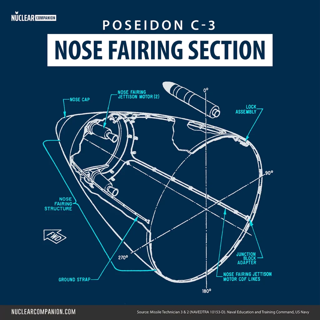
The Poseidon C3 missile’s nose fairing, attached to the forward end of the equipment section, served several key roles.
It enclosed the reentry subsystem, ensured hydrodynamic and aerodynamic stability, protected base frame components, and served as a primary structural element for hoisting during handling.
This bullet-shaped laminated wood shell, made of Sitka spruce, weighed about 183 pounds (37,6 kg) and measured 91 inches (231 cm) in length. It contained two motors specifically designed to jettison the fairing away from the equipment section and out of the missile’s flight path.
Further reading
Bibliography
- Missile Techician 3 & 2. (1979). United States: [Department of Defense, Navy Department], Naval Education and Training Program Development Center.
- Huck, J. A. (1986). Fire Control Technician B 3 & 2 (POSEIDON). United States: The Center.
- Sinusoidal vibration of Poseidon solid propellant motors, The Shock and Vibration Bulletin, Volume 42, 1972
- Techniques for Assessing Case Liner-Bond Integrity in Solid Propellant Rocket Motors. (1973). United States: Defense Technical Information Center.
- Alternate Propellant Program Phase I Final Report, JPL
- Ellis, R. A. (1976). Solid Rocket Motor Nozzles. United States: NASA.
- Naval War College Review. (1983). United States: Naval War College.
- Spinardi, G. (1994). From Polaris to Trident: The Development of US Fleet Ballistic Missile Technology. United Kingdom: Cambridge University Press.