Introduction
The Polaris Missile Mk 3 or Polaris A3 was a two-stage, solid-fuel, intermediate-range ballistic missile with inertial guidance, designed to deliver three warheads (reentry bodies) to targets up to 2,500 nautical miles away from the launch site. This missile could be launched from a submarine that was either surfaced or submerged.
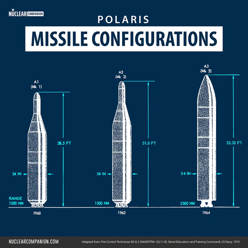
The initial Polaris missile, the Polaris A1 or Mk 1, was developed to be deployed as soon as possible until more advanced versions could be produced. From this foundational model, the subsequent Polaris missiles Mk 2 and Mk 3, as well as the Poseidon missile, were derived. The Polaris missile Mk 1 was retired from service in 1965, the Mk 2 was decommissioned in 1974, and the Mk 3 was phased out of U.S. Navy service in 1981.
Weapon System
Before continuing into the specifics of the Polaris A3 missile, let’s first understand the operation of the Polaris Fleet Ballistic Missile (FBM) Weapon System as a whole.
The Polaris Fleet Ballistic Missile (FBM) weapon system extended beyond the Polaris A3 missile alone. It comprised multiple essential subsystems:
- Ship System (598/608/616/627/640 class): The ship system supplied support services for the Fleet Ballistic Missile Weapon System and a stable launch platform for the Polaris A3 missile, both of which were crucial for a successful launch.
- Mk 2 Ships Inertial Navigation System (SINS) Mods 4 & 6: SINS served as the principal source of navigation data for the ship, fire control, and missile launching systems.
- Mk 3 Mods 4 & 5 Missile Test and Readiness Equipment (MTRE): The missile test and readiness equipment (MTRE) conducted preflight preparation and checkout for Polaris A3 missiles, carried out system and missile tests, and monitored the environmental conditions surrounding the missiles.
- Mk 80 Mods 2 & 3/ Mk 84 Fire Control System: The primary role of the fire control system (FCS) was to ready the 16 Polaris A3 missiles for launch at designated targets and to offer centralized control of the Weapon System.
- Mk 17 / Mk 21 Missile Launcher System: The missile launching system accommodated and safeguarded the 16 Polaris A3 missiles and executed their ejection during launch.
Submarine classes and tactical systems
The following table shows the designation of the tactical systems by mark number and class of submarine that carried the Polaris A-3 missile. The table is simplified and does not list the system modification number.
| SYSTEM | 598 | 608 | 616 | 627 | 640 |
|---|---|---|---|---|---|
| Navigation-SINS | Mk 2 | Mk 2 | Mk 2 | Mk 2 | Mk 2 |
| Fire Control System | Mk 80 | Mk 80 | Mk 84 | Mk 84 | Mk 84 |
| Missile | A-3 | A-3 | A-3 | A-3 | A-3 |
| Missile Launching System | Mk 21 | Mk 17 | Mk 17 / Mk 21 | Mk 21 | Mk 21 |
| MTRE | Mk 3 | Mk 3 | Mk 3 | Mk 3 | Mk 3 |
The 616, 627, and 640 class submarines were eventually all converted to the Mk 88 Fire Control System with Poseidon C-3 missile.
Physical description
The Polaris Missile A3 measured 32.3 feet (9.85 m) in length, had a diameter of 54 inches (137 cm) and weighed about 36,200 pounds (16,420 kg).
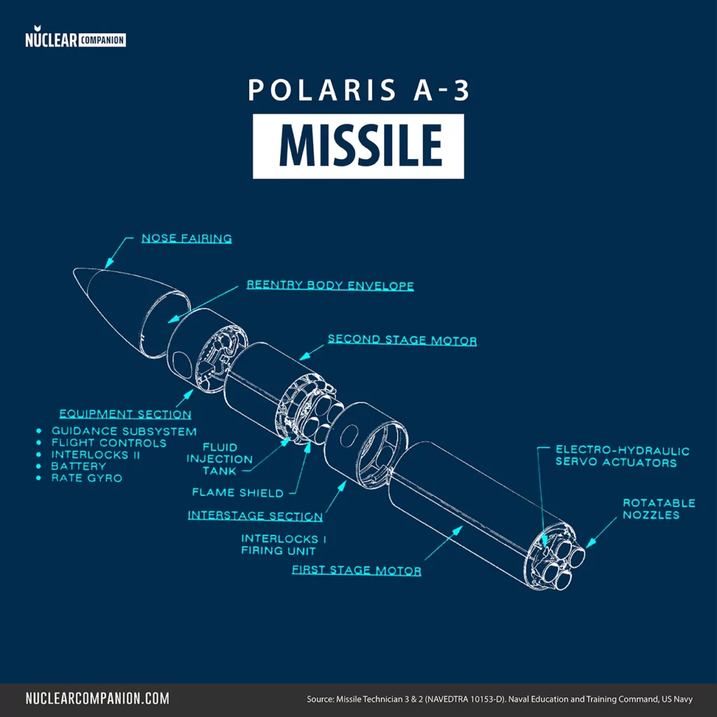
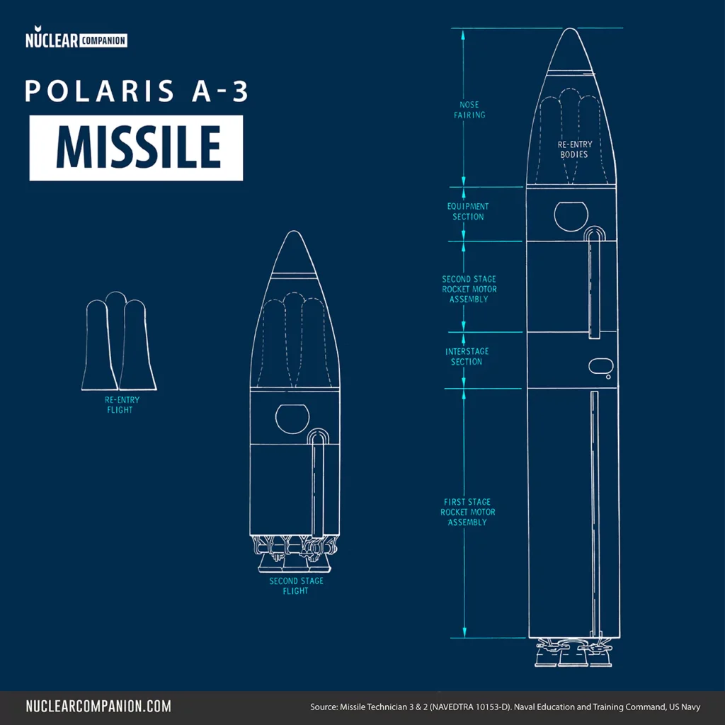
The missile was composed of a first-stage rocket motor assembly, an interstage section, a second-stage rocket motor assembly, an equipment section, a nose fairing, and a reentry subsystem.
First Stage Motor
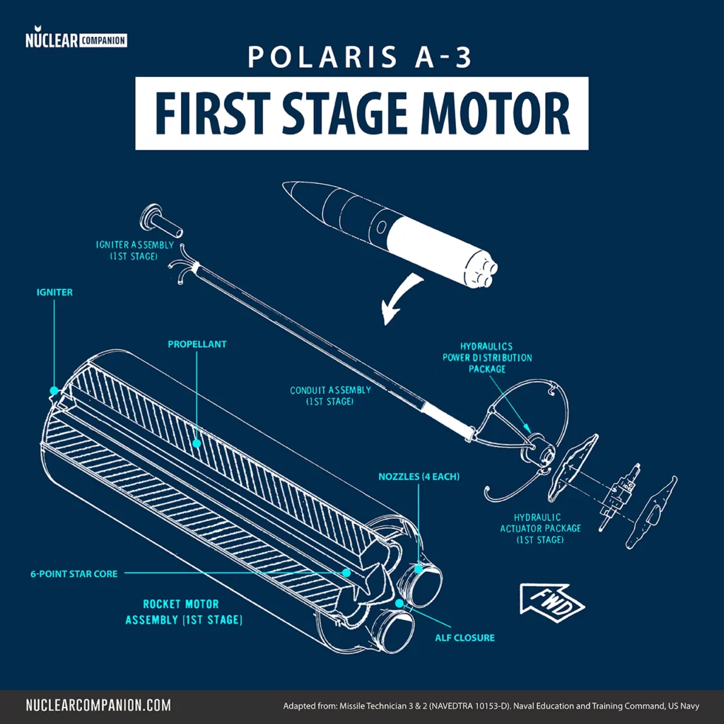
The first stage of the A-3 Polaris missile, developed by Aerojet General Corp. in Sacramento, California, accelerated the missile in the initial phase of the powered flight.
This stage consisted of a cylindrical rocket motor assembly that included the motor itself, an igniter, and four rotatable nozzles. The assembly was equipped with both electrical and hydraulic systems necessary for nozzle control and missile steering.
Constructed from a fiberglass, filament-wound case, the motor was filled with solid propellant.
The following table displays the First Stage Motor’s general characteristics:
| Attribute | Value |
|---|---|
| Chamber material (Fiber) | S-901 Fiberglass |
| Chamber Composite Stress Level (Psi) | 94,000 lbs / 42637.7 kg |
| Chamber Maximum Operating Pressure (Psi) | 940 lbs / 426.4 kg |
| Chamber Skirt/skirt Length | 155 in / 394 cm |
| Chamber Diameter | 54 in / 137.1 cm |
| Nozzles Number | 4 |
| Nozzle Throat Mail | Ag/W |
| Thrust vector control (TVC) | Rotatable |
| Nozzle Type | Graph Cloth Carbon Phenolic |
| Nozzle Weight (Each) | 365 lbs / 165.5 kg |
| Chamber/insul Weight | 1,547 lbs / 701.7 kg |
| Propellant Weight | 20,777 lbs / 9424.3 kg |
| Total Weight | 23, 895 lbs / 10838.6 kg |
Propellant
The first-stage rocket motor of the A-3 Polaris missile utilized a single-base type solid propellant known as ANP-2969, a nitro-plasticized polyurethane blend. This compound included ammonium perchlorate and aluminum, optimized for intense energy release. The propellant was cast into the motor’s core in a six-pointed star configuration to enhance the burning rate effectively.
Upon ignition, the propellant generated extreme temperatures up to 6,000 °F and significantly increased pressure levels. This high-intensity combustion compelled Lockheed to reinforce the motor’s nozzles with silver-infiltrated tungsten to withstand the harsh thermal and mechanical stress.
However, this modification added weight to the nozzles, decreasing the missile’s range by 90 nautical miles and necessitating a doubling of the hydraulic system’s power to counteract the resultant engine torque and maintain precise missile control.
The following table displays the ANP 2969 composition:
| Ingredient | Function | Mass% |
|---|---|---|
| Ammonium perchlorate | Explosive Oxidant | 55 |
| Al powder | Fuel | 20 |
| Bis (dinitro-propyl acetal / formal), BDNPA/F | Energetic plasticiser | 12.5 |
| Polyoxyethylene glycol (PEG) / trimethylolpropane (TMP)/ TDI-crosslinked polyurethane | Binder | 12.5 |
Trust Vector Control
The first stage’s thrust vector control (TVC) system incorporated four rotatable nozzles, originally developed for the second stage of the A2 model, to manage the missile’s pitch, yaw, and roll during the initial phase of flight. These nozzles were hydraulically powered and connected to actuators that responded to control signals from the missile’s onboard electronics package.
The unique design of the nozzles featured an axis of rotation set at an angle, allowing for pure axial thrust in their neutral position. Upon rotation, the nozzles could deflect the jet stream relative to the motor’s centerline, enabling effective vector control with minimal loss of axial thrust.
Strategic rotation of two opposite nozzles either in the same direction produced a lateral force, or in opposite directions generated a roll-control torque, thus facilitating precise directional and stabilizing adjustments throughout the flight.
Interstage Section
The Polaris A3 missile’s interstage section served as the juncture between the first and second-stage rocket motors. This cylindrical shell, constructed from a magnesium-thorium alloy (HK31A-H24) with less than 3 percent thorium, was engineered to both protect and support critical missile components. These included the first-stage ignition and separation devices, a hydraulics battery package, the second-stage thrust-vector control system, and interlocks I.
The interstage section was designed with a skin thickness of 0.406 centimeters (0.160 inches) and a diameter of 137.2 centimeters (54 inches), with a height of approximately 85.1 centimeters (33.5 inches) excluding the aluminum attachment rings.
It featured two access ports that allowed for maintenance and inspection of all internal elements. A detonating cord installed around the forward circumference facilitated the separation of the first stage and interstage from the missile following first-stage burnout, ensuring a smooth transition in the flight sequence.
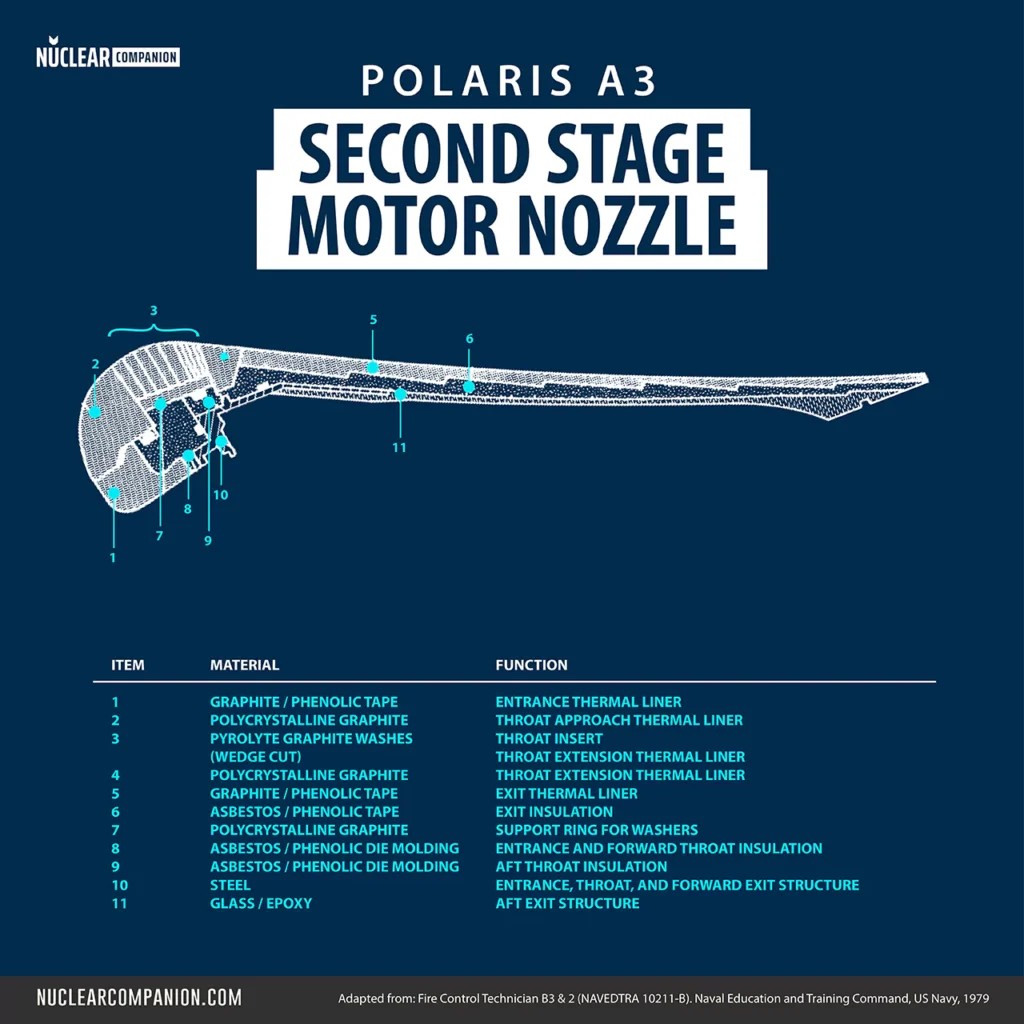
Second Stage Motor
The second stage of the Polaris A3 missile, manufactured by Hercules Powder Company in Bacchus, Utah, propelled the missile from the point of first-stage separation to the velocity necessary for positioning the reentry subsystem into its designated ballistic trajectory.
This stage consisted of a cylindrical rocket motor assembly which comprised the motor itself, an igniter, and four fixed nozzles.
The motor chamber was a fiberglass, filament-wound case, which was densely packed with solid propellant to ensure efficient burn and thrust. The assembly was also equipped with electrical systems and a Freon injection setup for navigation and control of the missile. These components adjusted the nozzle thrust and steered the missile accurately along its planned course.
The following table displays the Second Stage Motor’s general characteristics:
| Attribute | Value |
|---|---|
| Chamber material (Fiber) | S-901 Fiberglass |
| Chamber Composite Stress Level (Psi) | 115,000 lbs / 52163.1 kg |
| Chamber Maximum Operating Pressure (Psi) | 400 lbs / 181.4 kg |
| Chamber Skirt/skirt Length | 55 in / 139.7 |
| Chamber Diameter | 54 in / 137.1 cm |
| Nozzles Number | 4 |
| Nozzle Throat Mail | ATJ |
| Thrust vector control (TVC) | Fluid Injection |
| Nozzle Type | Graph Cloth Glass Phenolic |
| Nozzle Weight (Each) | 43 lbs / 19.5 kg |
| Chamber/insul Weight | 410 lbs / 186 kg |
| Propellant Weight | 8,844 lbs / 4011.6 kg |
| Total Weight | 9,492 lbs / 4305.5 kg |
Propellant
The second stage of the Polaris A3 missile utilized a composite-modified double-base (CMDB) propellant formulation known as EJC.
The composition of EJC included a high-energy explosive called HMX, along with a mixture of ammonium perchlorate, nitrocellulose, nitroglycerine, and aluminum. These components were chosen for their energetic properties and stability, providing a specific impulse of 280 seconds.
Hercules cast the propellant into a slotted, cylindrical central cavity with an eight-point star configuration at the center and a unique “snowflake” or “Christmas tree ornament” cross-section at the aft end of the stage to ensure a more uniform burn.
Trust Vector Control
The second stage of the Polaris A3 missile featured an innovative thrust vector control (TVC) system that utilized a fluid injection technique for steering.
This system marked a departure from traditional movable nozzle designs, employing pressurized Freon injected directly into the exhaust stream of four fixed nozzles. The mechanism was both lightweight and less sensitive to flame temperature variations, providing a significant advantage in terms of performance and reliability.
The system was operated by injecting Freon 114 into the exit cone of each nozzle through metering valves mounted on their external surface. This injection created a shock pattern that deflected the main exhaust stream, thereby altering the missile’s trajectory for pitch, yaw, or roll control.
For directional adjustments, Freon was injected into two selected nozzles, while roll adjustments required simultaneous injection into all four nozzles. The resultant oblique shock wave effectively manipulated the thrust vector, enabling precise control over the missile’s orientation and flight path.
Moreover, the fluid management system was specifically designed to ensure optimal utilization of Freon during flight, including the jettisoning of excess fluid to minimize weight and preserve balance.
Equipment Section

The equipment section of the Polaris A3 missile served as the central hub for the various systems required for both stages of the missile’s flight. This cylindrical shell, constructed from a magnesium-thorium alloy, was located forward of the second-stage motor and connected directly to the reentry subsystem and nose fairing.
It housed and protected crucial missile components, including the flight-control electronics, rate gyro package, electronics battery, power distribution package, guidance electronics, the guidance gimbal assembly, and Interlocks II.
Additionally, this section contained the main umbilical receptacle, the igniter for the second-stage rocket motor, separation devices for the nose fairing and reentry subsystem, and the ignition inverter. All these components were readily accessible through the guidance subsystem access door.
Guidance Subsystem

The Polaris A3 was equipped with the Mk 2 guidance system which was responsible for the precise navigation and control of the missile during its powered flight phase.
Developed at the Massachusetts Institute of Technology’s Instrumentation Laboratory, this system utilized inertial guidance technology to direct the missile’s trajectory and manage the separation and ejection of the reentry bodies.
During the powered portion of the flight, the Mk 2 guidance system calculated and imparted a specific velocity to the reentry body, ensuring it followed a ballistic trajectory that would lead it directly to the predetermined target without further guidance.
This capability was facilitated by a special-purpose digital computer within the guidance system, which performed real-time calculations based on continuous performance data from the missile and pre-set trajectory information. The resulting control signals were then dispatched to various missile subsystems to adjust flight parameters as necessary.
The guidance subsystem included the guidance gimbal assembly, the guidance electronics assembly, and a heat exchanger.
Gimbal Assembly
The Gimbal Assembly was composed of three main components: an outer gimbal, a middle gimbal, and an inner gimbal, which housed the stable platform. On this stable platform sensitive motion-sensing and acceleration-detection devices were mounted, ensuring the missile’s trajectory aligned precisely with the intended target.
Mounted on this stable platform were three inertial rate-integrating gyroscopes (IRIGs). These, each 2.5 inches in diameter, were modified beryllium gyroscopes with spherical rotor and magnetic suspension.
These IRIGs detected any motion of the missile about its computing axis and converted these movements into electrical signals. The guidance computer used these signals to make real-time adjustments during flight.
Additionally, the platform supported two 1.6-inch in diameter Pulsed Integrating Pendulous Accelerometers (PIPAs) and one 1.6-inch in diameter Pendulous Integrating Gyro Accelerometer (PIGA), each responsible for providing detailed acceleration data.
Guidance Assembly Electronics
The electronics assembly included the electronics for the gimbal servo loops and the accelerometers, power supplies, a prearm inhibitor module, and the guidance computer, which processed and executed flight commands.
The guidance computer utilized velocity data from the accelerometers to generate pitch and yaw steering commands for the missile. These commands adjusted the missile’s attitude during flight. Additionally, the computer calculated the “velocity-to-be-gained,” which determined the precise moments for prearm and cutoff conditions, essential for the timing of warhead arming and engine shutdown.
Technologically, the guidance computer employed silicon planar transistors and introduced a novel approach to component packaging: welded cordwood. This included welded-wire interconnections within modules and wire-wrap connections between modules, a method that significantly reduced the size of the computer system compared to traditional printed circuit boards.
The following table displays the guidance computer characteristics
| Architecture | Wired program DDA |
| Memory | Magnetic core shift register |
| Words | 12 |
| Word length | 17 bits |
| Logic | 512 transistor NOR gates |
| I/O | Incremental data transfer |
| Clock rate | 81.6 kHz |
| Size | 0.1 ft3 (2832 cm3) |
| Weight | 12 lb (5.4 kg) |
| Power | 40 W |
The design utilized a simplified logic architecture, based solely on a three-input NOR gate for all logic operations, which streamlined the assembly and reduced complexity.
Memory storage in the computer was managed by magnetic cores configured as 17-bit shift registers. These cores were made of a ferromagnetic material that maintained its magnetization state, similar to coincident-current memory systems.
The memory architecture included two modules, each containing six registers, for a total of 12 words of memory. This setup was complemented by memory driver modules, eight logic modules, a clock module, and an input/output module.
Reentry Subsytem
The reentry subsystem included three Mk 2 reentry bodies along with separation and ejection equipment, which were mounted to the base structure of the equipment section and enclosed by the nose fairing.
Upon receiving a command from the guidance subsystem, the reentry bodies separated from the second-stage propulsion system and entered a free-fall ballistic trajectory toward the target. The ejection process involved three individual rockets that not only propelled the warheads away from the main flight path but also imparted a stabilizing spin to each, enhancing their aerodynamic stability during reentry.
To optimize survivability against anti-ballistic missile (ABM) defenses, the warheads were ejected sequentially, approximately one second and one nautical mile apart. This strategic spacing was designed to prevent a single ABM attack from destroying multiple warheads simultaneously and to minimize interference from the explosive effects of nearby detonations.
The Mk2 reentry body (RB)
The Mk2 reentry body, equipped with a thermonuclear W58 warhead, featured an elliptical nose shape crafted from beryllium and a nylon-phenolic ablative heat shield over an aluminum structure. Each reentry body measured 54 inches in length (137 cm), had a maximum diameter of 23.5 inches (59.7 cm) at the flared base, and weighed 309 pounds (140 kg).
Each of the three W58 warheads, designed by the Lawrence Livermore National Laboratory, had a yield of 200 kilotons. The warheads for the UK Polaris missiles, known as ET.317, were developed domestically by the British.
Nose Fairing Section

The Polaris A3 missile’s nose fairing was designed to shield the reentry bodies and sensitive equipment during the initial phases of flight.
Constructed from a combination of laminated wood and aluminum, this bullet-shaped enclosure was attached to the forward circumference of the equipment section. Its primary roles included providing hydrodynamic and aerodynamic stability, which were critical during the launch and boost phase, and protecting the internal components from environmental stresses.
In addition to its protective functions, the nose fairing was engineered with attach rings and a jettison rocket. The attach rings facilitated vertical hoisting of the assembled missile during handling and transfer operations. Following the first-stage separation and before the ejection of the reentry subsystem, the nose fairing was swiftly and efficiently removed from the missile’s trajectory by the jettison rocket.
Further reading
Bibliography
- Missile Techician 3 & 2. (1979). United States: [Department of Defense, Navy Department], Naval Education and Training Program Development Center.
- Spinardi, G. (1994). From Polaris to Trident: The Development of US Fleet Ballistic Missile Technology. United Kingdom: Cambridge University Press.
- Solid Rocket Motor Nozzles. NASA SP-8115, 126 pages, published by NASA, Washington, D.C., 1975
- Hall, E. C. (1996). Journey to the moon: the history of the Apollo guidance computer. Reston: American Institute of Aeronautics and Astronautics.
- Goetz, P. A. (2020). A Technical History of America’s Nuclear Weapons: Volume II – Developments from 1960 Through 2020 – Second Edition
 to targets up to 2,500 nautical miles away from the launch site. This missile could be launched from a submarine that was either surfaced or submerged.)
Thanks for the information I was a FTB1(ss) on the Thomas Edison and made eight patrols from 1975-80. Got to fire missile 11 at a test where we went below the equator and shot to the north. Just recently joined the Holland Club indication it has been fifty years since I earned my dolphins.
Thanks,
Scott Thompson