Mission
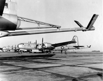
The KB-29P aircraft’s primary purpose was to perform in-flight refueling of other planes using the flying boom method. It differed from the standard B-29 plane by eliminating all defensive armament and installing specialized in-flight refueling equipment.
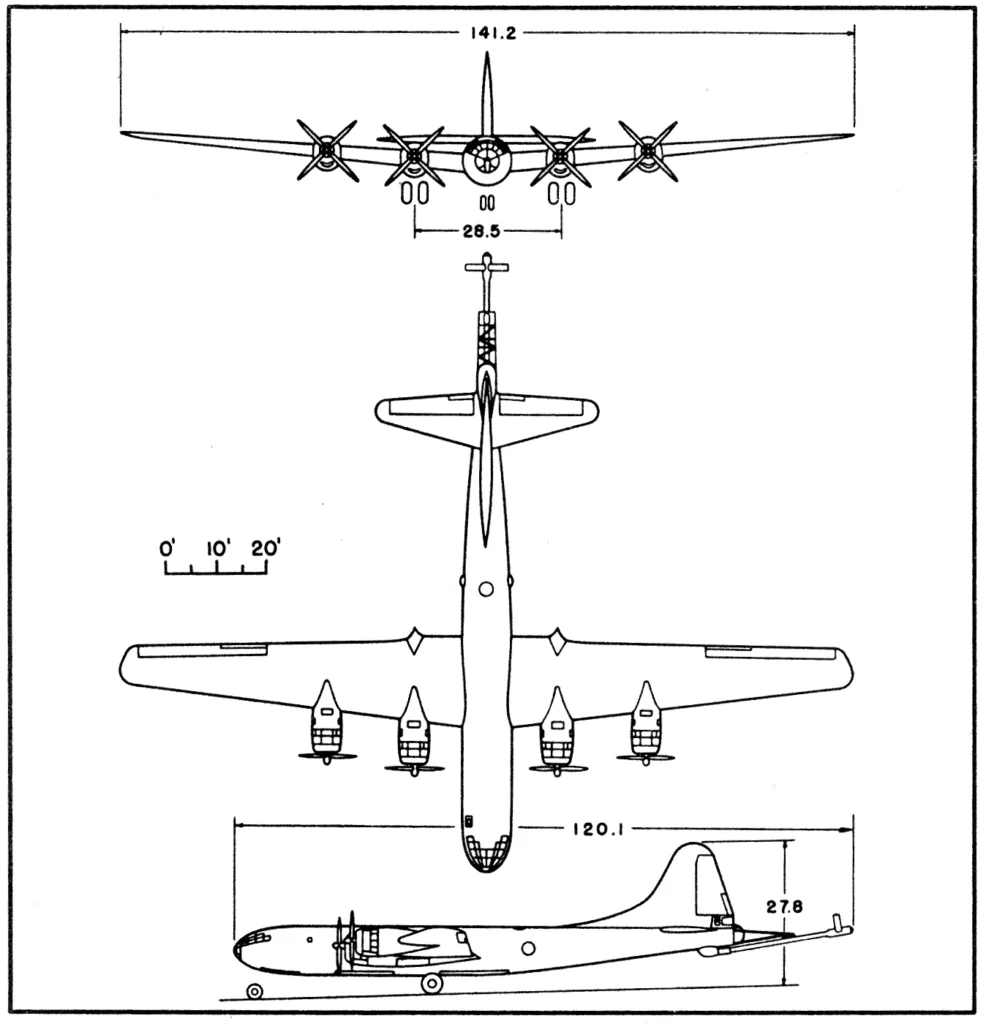
Dimensions and Weights
| DIMENSIONS | Imperial | Metric |
|---|---|---|
| Wing | ||
| 141.2 ft | 43 m | |
| 4° | 4° | |
| 4°29'23" | 4°29'23" | |
| 7°1'26" | 7°1'26" | |
| 1720 ft2 | 159.8 m2 | |
| 11.5 | 11.5 | |
| Boeing 117 | Boeing 117 | |
| 154.41 | 47.1 m | |
| Length | 120.1 ft | 36.6 m |
| Height | 27.8 ft | 8.5 m |
| Tread | 28.5 ft | 8.7 m |
| Prop. Grd Clearance | 1.3 ft | 0.4 m |
| WEIGHTS | ||
| Loading | ||
| 69,011 lbs (E) | 31.303 kg | |
| 70,645 lbs (A) | 32.044 kg | |
| 74,705 lbs | 33.886 kg | |
| 135,000 lbs | 61.235 kg | |
| 84,665 lbs | 38.403 kg | |
| 138,500 lbs | 62.823 kg | |
| 135,000 lbs | 61.235 kg |
(E) Estimated
(A) Actual
(*) For basic mission
(1) Limited by performance
(2) Limited by gear strength
Engines
| Attribute | Value |
|---|---|
| POWER PLANT | |
| (4) R-3350-57 or-57A | |
| Curtiss - Wright Corp., Wright Aeronautical Corp. Division | |
| 95-28266-5 | |
| (2) B-31 | |
| General Electric Co. | |
| 0.35 | |
| PROPELLER | |
| Curtiss - Wright Corp. | |
| 1016-4C4-18 | |
| CS, FF, Reverse, | |
| 4 | |
| 16' 8" (5.1 m) | |
| ENGINE RATINGS | |
| 2200bhp/2800rpm | |
| 2200bhp/2600rpm/2500ft | |
| 2000bhp/2400rpm/4000ft |
Electronics
| Equipment | US Designation |
|---|---|
| VHF Command | AN/ARC-3 |
| Command | SCR-274N |
| Interphone | AN/AIC-2 |
| Liaison | AN/ARC-8 |
| Radio Compass | AN/ARN-7 |
| Marker Beacon | RC-193A |
| Radar | AN/APQ-13A |
| Loran | AN/APN-9 |
| IFF | SCR-695B |
| Rendezvous Radar | AN/APN-2B,AN/APN-68 and AN/APN-11 |
Crew
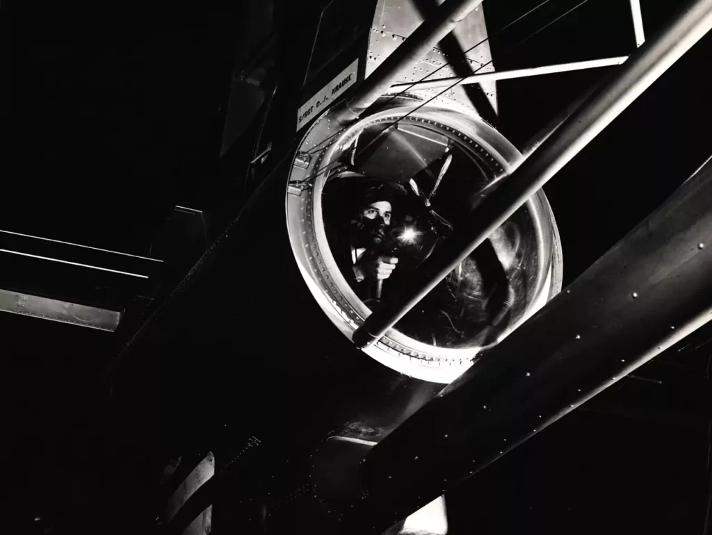
The KB-29P had a new crew member in the form of a boom operator who was responsible for operating the boom and connecting it to a receiver aircraft receptacle. This crew member sat in the converted tail turret position of the B-29.
The crew list for the KB-29P was:
- Pilot
- Co-pilot
- Navigator
- Flight Engineer – Pumping system operator
- Radio operator
- Radar operator
- Flying Boom operator
Fuel
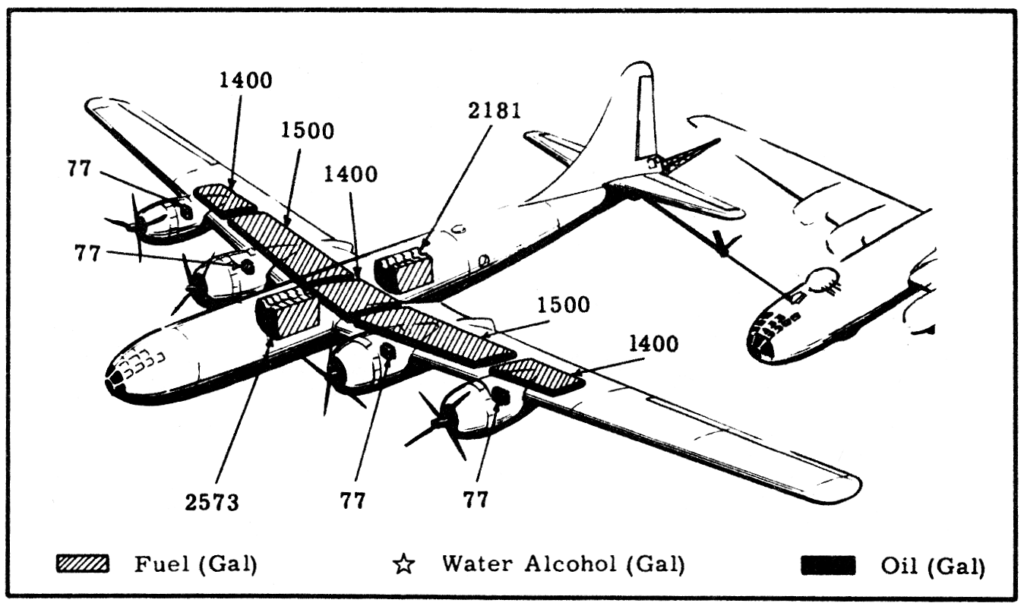
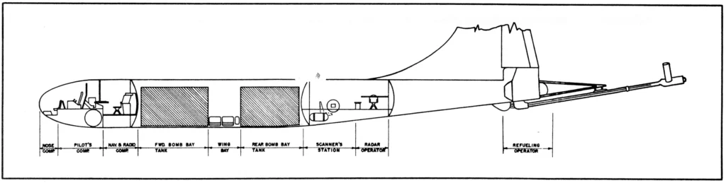
The KB-29P included form-fitting bomb bay tanks, each of which was jettisonable. All fuel tanks in the KB-29P tanker were made up of nylon non-self-sealing cells. The aircraft had a maximum fuel capacity of 11,954 gallons, which was greater than that of the B-29 bomber, which was 9,363 gallons.
Initially, all fuel tanks were serviced with Mil-F-5572 aviation gasoline, which was available in two grades – 100/130 or 115/145. However, when the KB-29Ps were later used to refuel jet aircraft, the fuel servicing strategy was changed. The four main wing tanks and the two bomb bay tanks were restricted to the use of aviation gasoline, while the wing center section tanks were serviced with JP-4 jet fuel.
| Location | No. Tanks | Gal | Liters |
|---|---|---|---|
| Wing, outbound * | 2 | 2800 | 10.599 |
| Wing, inbound * | 2 | 3000 | 11.356 |
| Wing, center | 1 | 1400 | 5300 |
| Bomb bay, forward* | 1 | 2573 | 9740 |
| Bomb bay, afterward* | 1 | 2181 | 8256 |
| Total | 11,954 | 45.251 |
(*) nylon non-self-sealing cells
Refueling Equipment
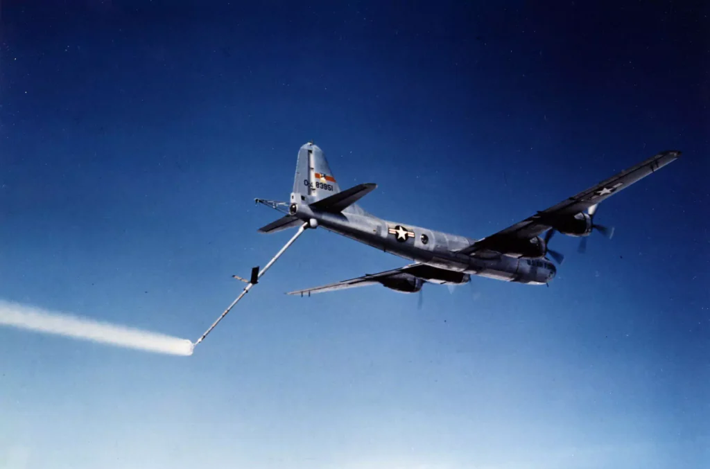
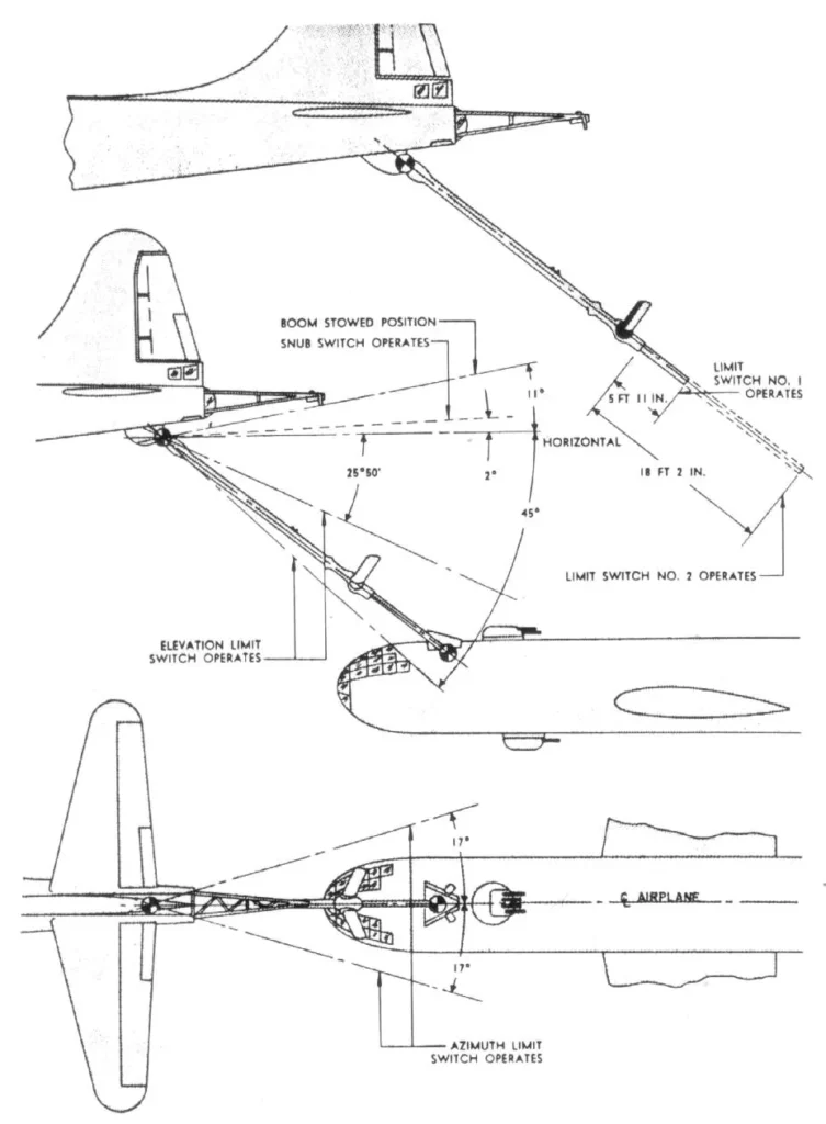
A maneuverable telescoping boom with an articulated nozzle is attached to the bottom of the fuselage near the tail, serving as a connection and medium for fuel transfer between the tanker and receiver aircraft. The boom operator’s compartment (formerly the tail gunner’s compartment) houses hydraulic and aerodynamic controls for the boom.
The fuel system comprises a manifold system for normal operations and a high-capacity pump system for refueling. With the exception of the hydraulically-operated brakes and boom, all equipment is operated electrically.
The list of refueling equipment is the following:
- Telescopic Flying Boom
- Articulated Boom Nozzle
- Ruddevators for aerodynamic control
- Signal Amplifier
- Radar equipment necessary for rendezvous with receiver:
- AN/APN-2B
- AN/APN-68
- AN/APN-11
Refueling Operation process:
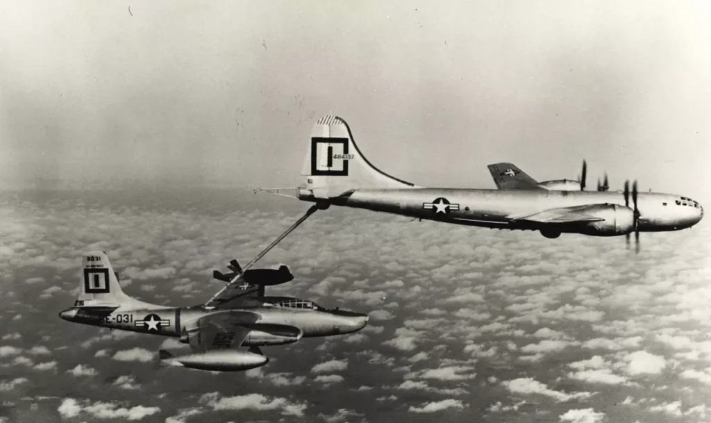
The KB-29P’s refueling operations were carried out with precision, requiring coordinated crew activities and careful formation flying.
- The KB-29P aircraft would assume a cruising altitude, extending the boom, and positioning the receiver aircraft below and behind the tanker.
- The boom operator would then guide the boom into the receptacle via ruddevator flight surfaces, which the boom operator manipulates using a conventional control stick. Contact is detected by a signal amplifier that controls equipment based on aircraft positions, rate of position change, and refueling line fuel pressure.
- Then, the flight engineer and boom operator would work together to transfer fuel into the receiver aircraft. The tanker is equipped to supply fuel to the receiver plane at a selectively controlled rate, up to 600 gallons per minute.
- During the fuel transfer, the receiver pilot would use the indicator lights, which displayed RIGHT, LEFT, UP, DOWN, FORWARD, and AFT, to make minor attitude adjustments and maintain position. As the weights of the two aircraft changed, and the center of gravity shifted, these adjustments became necessary.
- If any predetermined limits are exceeded, an involuntary disconnect is automatically triggered. A voluntary disconnect may also occur, initiated either by the boom operator or receiver pilot, resulting in a fuel shut-off and boom disconnect.
- Once refueling was complete, the receiver aircraft would drop off the boom. The boom operator would purge the refueling manifold with nitrogen to prevent any trapped fuel from causing an explosion.
Performance
The basic performance of the KB-29P was the following:
Combat radius
1000 nm
with 35,000 lb of transfer fuel at 216 knots avg. in 16.90 hours
Combat range
1594 nm
with 35,000 lb of transfer fuel at 204 knots avg. in 9 hours
Combat speed
288 kn
at 10,000 ft alt, max power
Maximum speed
349 kn
at 30,000 ft alt, max power
Climb
500/2135
fpm sea level, take-off weight normal power
/fpm sea level, combat weight max power
Ceiling
23,500/
39,500 ft
100 fpm, take-off weight, normal power
/500 fpm, combat weight max power
Loading and Performance – Typical mission
| Conditions | Basic Mission | High Alt Refuel | Ferry range | |||
|---|---|---|---|---|---|---|
| TAKE-OFF WEIGHT | 138,500 lbs | 62.823 kg | 138,500 lbs | 62.823 kg | 138,500 lbs | 62.823 kg |
| 28,795 lbs | 13.061 kg | 35,271 lbs | 15.999 kg | 63,795 lbs | 28.937 kg | |
| 35,000 lbs | 15.876 kg | 28,524 lbs | 12.938 kg | None | ||
| 80.5 lb/sq ft | 393 kg/m2 | 80.5 lb/sq ft | 393 kg/m2 | 80.5 lb/sq ft | 393 kg/m2 | |
| 103 kn | 191 km/h | 103 kn | 191 km/h | 103 kn | 191 km/h | |
| 5,075 ft | 1.547 m | 5,075 ft | 1.547 m | 5,075 ft | 1.547 m | |
| 7,570 ft | 2.307 m | 7,570 ft | 2.307 m | 7,570 ft | 2.307 m | |
| 500 fpm | 152,4 m/min | 500 fpm | 152,4 m/min | fpm | 152,4 m/min | |
| 23. 8 min | 23. 8 min | 23. 8 min | ||||
| 61.8 min | 61.8 min | 61. 8 min | ||||
| 23,500 ft | 7.163 m | 23,500 ft | 7.163 m | 23,500 ft | 7.163 m | |
| 19,000 ft | 5.791 m | 19,000 ft | 5.791 m | 19,000 ft | 5.791 m | |
| COMBAT RANGE (4) | 1594 n.mi. | 2952 km | 1957 n.mi. | 3624 km/h | 4987 n.mi. | 9236 km/h |
| 204 kn | 378 km/h | 204 kn | 378 km/h | 192 kn | 356 km/h | |
| 10,000 ft | 3.048 m | 10,000 ft | 3.048 m | 10,000 ft | 3.048 m | |
| 10,000 ft | 3.048 m | 25,000 ft | 7.620 m | 10,000 ft | 3.048 m | |
| 9.00 hrs | 10.74 hrs | 26.13 hrs | ||||
| COMBAT RADIUS (4) | 1000 n.mi. | 1852 km | 1154 n.mi | 2137 km | ||
| 190 kn | 352 km/h | 211 kn | 391 km/h | |||
| 10,000 ft | 3.048 m | 10,000 ft | 3.048 m | |||
| 10,000 ft | 3.048 m | 25,000 ft | 7.620 m | |||
| 248 kn | 459 km/h | 311 kn | 576 km/h | |||
| 10,000 ft | 3.048 m | 25,000 ft | 7.620 m | |||
| 11.71 hrs | 12.08 hrs | |||||
| COMBAT WEIGHT (5) | 84,665 lbs | 38.403 kg | 86,120 lbs | 39.063 kg | 81,085 lbs | 36.780 kg |
| 10,000 ft | 3.048 m | 25,000 | 7.620 m | 10,000 ft | 3.048 m | |
| 288 kn | 533 km/h | 332 kn | 615 km/h | 290 kn | 537 km/h | |
| 2,025 fpm | 617.2 m/min | 1,735 fpm | 529 m/min | 2,160 fpm | 658.3 m/min | |
| 39,500 ft | 12.040 m | 39,200 ft | 11.948 m | 40,450 ft | 12.329 m | |
| 42,900 ft | 13.076 m | 42,500 ft | 12.954 m | 43,800 ft | 13.350 m | |
| 38,800 ft | 11.826 m | 38,450 ft | 11.720 m | 39,700 ft | 12.101 m | |
| 2,135 fpm | 650,7 m/min | 2,080 fpm | 634 m/min | 2,275 fpm | 693,4 m/min | |
| 349 kn | 646 km/h | 348 kn | 644 km/h | 350 kn | 648 km/h | |
| LANDING WEIGHT (5) | 76,145 lbs | 34.539 kg | 76,469 lbs | 34.686 kg | 81,085 lbs | 36.780 kg |
| 2,060 ft | 628 m | 2,075 ft | 1.547 m | 2,175 ft | 663 m | |
| 2,750 ft | 838 m | 2,760 ft | 841 m | 2,890 ft | 881 m | |
(1)Take-off power
(2) Max power
(3) Normal power
(4) Detailed descriptions of RADIUS and RANGE missions are given on page 6.
(5) For Radius Mission if the radius is shown
(6) At normal rated power but not exceeding 250 MPH (EAS) as per T. O. AN 01-20EJAB-1 NOTES 1
Further reading
- Boeing B-29 Superfortress Specifications (1950)
- Boeing B-29A Superfortress Specifications (1950)
- Boeing B-29B Superfortress Specifications (1950)
- Boeing SB-29 Superfortress Specifications (1954)
- Tupolev Tu-4 Standard Specification & Performance
- Boeing B-29 Superfortress Facts: 11 things to know
Bibliography
- B-29 Superfortress in detail & scale, Part 2: Derivatives by Alwyn T. Lloyd
- KB-29P Superfortress SAC 8-MAR-1951, Air Materiel Command, U.S. Air Force